
II. FROM OPTICAL TO VISUAL EFFECTS
23. ACUITY AND THE EYE
Receptor size should determine the smallest distance between two lines that keeps them distinct. Yet matters are not that simple.
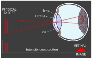 Ideally, the lens focuses photons to a fine point. However, diffraction of photons from the effective edge of that lens limits the focus to a spot (Airy disk) whose size increases as wavelength increases and decreases as lens size increases:
Generally, this disk is about twice the size of a cone photoreceptor. [1]
But that’s only a small part of the problem.
(This is a good place to point out that the eye’s lens has two structures that do the focusing. The cornea is the curved front of the eye. It does most of the focusing. The lens sits behind the cornea. It can be squeezed to increase its curvature for a closer focus. Unless there is a need to distinguish them, we shall continue to call them a “lens”.)
Photons get scattered as they pass through the cornea, the lens, and fluids inside the eye. These structures and fluids are not perfectly transparent and deteriorate with age. [2] On reaching the retina, the rays must pass through blood capillaries, ganglion cells, bipolar cells, other neurons, and most of the photoreceptor’s cell body before reaching the light absorbing pigments at the back of the cell. [3] Ordinarily, much of this structural scatter is constant and gets “corrected” by memory and further processing.
However, the scattering of photons in the retinal image becomes evident when lighting conditions contrast strongly in brightness.
We are all familiar with glare reflected off TV screens and shiny surfaces. Here is an extreme example from headlights and road reflections:
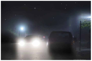
Eye-caused glare is easily confused with glare caused by mist and fog.
In this photo, the detail evident in its dim light sources (the stars, leaves, poles, and a distant window) indicates that the glare is in the eye and not atmospheric.
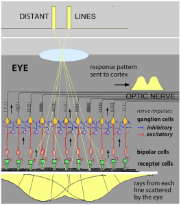
The visual system uses lateral inhibition processing to correct the ever-present blurring of the retinal image. It works like this:
Inhibition between adjacent receptor pathways results in the strongest stimulated pathway inhibiting the response in weaker adjacent pathways.
This “winner takes all” effect sharpens the signal sent to the brain. If you think this neural network is similar to how the 6 on-off concentric opponent-color pathways are organized – Bravo!
This process along with the color and light-dark adaptation processes all overlap in that ½ millimeter thick retinal tissue at the back of your eye!
In some circumstances, lateral inhibition is directly revealed when edges are produced by modest differences in brightness between otherwise uniform areas:

The extra light region in a lighter band immediately above a darker band is due to less inhibition from below.
As the lighter band is extended beyond the darker band, the extra lightness vanishes. The extra dark region at the top of a dark band below a lighter band isdue to lateral inhibition from the lighter band.
Together, these two aspects make edges between two areas of the retinal image more evident than they “actually” are.
This bit of “deception” is all part of how the system uses neural processing to overcome optical and physiological limits to represent the world more accurately.
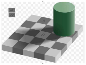 The Adelson illusion is a striking example that reveals the visual system’s use of broader patterns to create images that represent the physical world more accurately than optical images on the retina:
Squares A and B reflect the same amount of light. Yet, if they appeared identical, the checkerboard pattern would be ruined.
Skeptical?
On a white card punch two holes separated by the distance between squares A and B. Hold that in front of this figure so that you only see squares A and B.
It is impossible to believe that squares A and B in the checkerboard are equally grey. Yet their copies in the upper left corner show that they are produced by the same illumination on the retina. Evidently, cognitive recognition of the checkerboard pattern reinforces the strength of this “illusion”.
- The inverse relation between lens (and mirror) size and Airy disk size is why larger telescopes provide sharper as well as brighter images ↵
- The lens has a complex molecular structure. It is vulnerable to deterioration that reduces its clarity. This results in blurred vision - cataracts. This blurring is readily corrected by replacing the lens. During fetal development the lens is nourished by a vascular canal from the retina though the eyeball to the lens - hyloid canal. It has usually disintegrated by birth, but fragments remain in the vitreous humor. They tend to settle out of the way. However, eye movements can set them adrift. Because the visual system can’t compensate for their moving shadows, they are seen as dark “floaters” superimposed on the visual image. ↵
- The end tips of the photoreceptors are imbedded in a black matrix. This makes their response more specific to their location by preventing stray light on either side from reaching their photopigments. ↵