
Chapter 5: Trusses
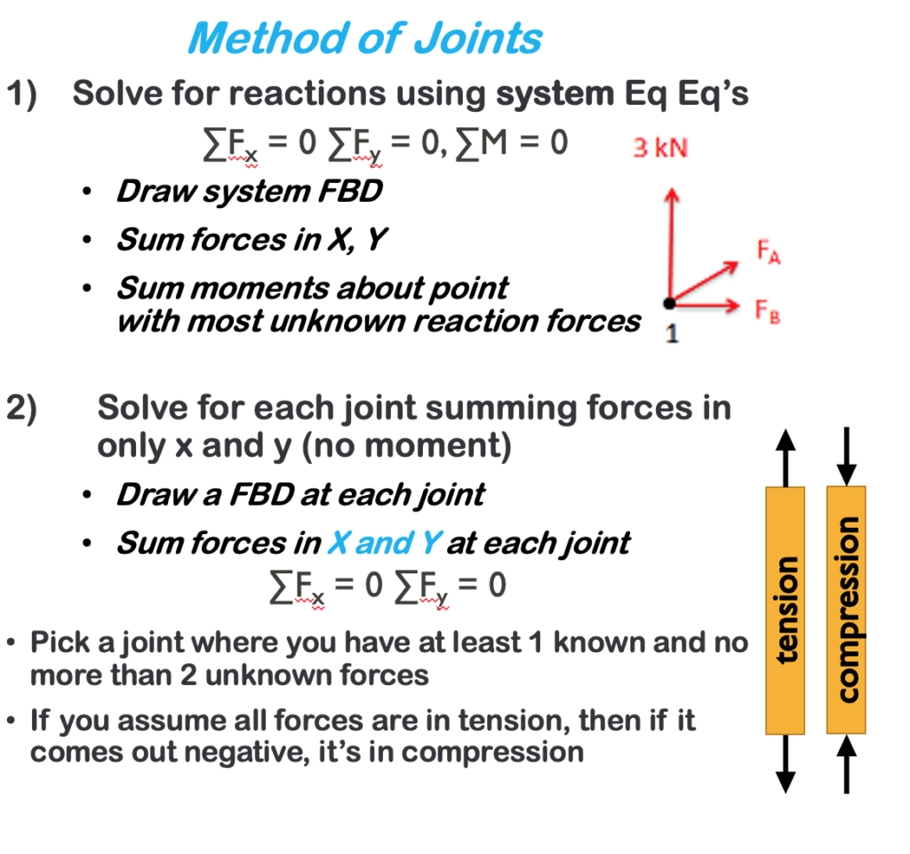
5.2 Method of Joints
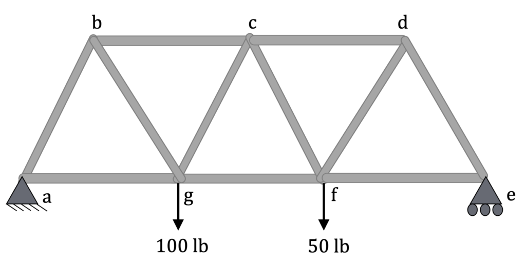
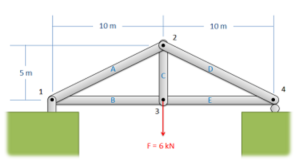
The method of joints is a form of particle analysis. After solving for the reaction forces, you solve for the unknown forces at each joint until you have found the value of each member. You start with your model:
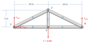
Convert the constraints into reaction forces with the appropriate labels:
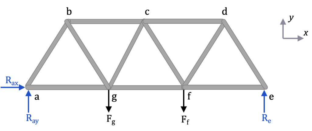
Now solve for the reaction forces (Rax Ray Re) looking only at the external forces using the equilibrium equations for a rigid body:
[latex]\sum F_x=0\\\sum F_y=0\\\sum M=0[/latex]
Assuming the length of each member is L:
[latex]\sum F_x=R_{ax} = 0, \\\underline{R_{ax} = 0}[/latex]
[latex]\sum F_y=R_{ay}+R_e – F_g - F_f= 0, \\R_{ay} +R_e = 150 lb[/latex]
[latex]\sum M_a= -L*F_g – 2L * F_f+3L*R_e = 0\\R_e = \frac{100L + 100L}{3L}\\\underline{R_e =66.7 lb}[/latex]
[latex]R_{ay} = 150 lb - 66.7 lb\\ \underline{ R_{ay}= 83.3 lb }[/latex]
Next, pick a joint where there are 2 or fewer unknown values, such as a or e. This is because you only have 2 equations available to find the unknowns: [latex]\sum F_x=0 \text{, } \sum F_y=0[/latex]. The following table shows the number of known and unknown forces at each joint.
| Joint: | a | b | c | d | e | f | g |
| Known forces: | 2 | 0 | 0 | 0 | 1 | 1 | 1 |
| Unknown forces: | 2 | 3 | 4 | 3 | 2 | 4 | 4 |
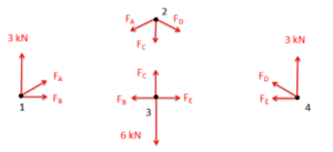
Choosing joint a (or e), do a particle analysis, assuming all of the members are in tension. That way, if the force is negative, that means it is in compression. Notice Rax has been excluded because it is equal to zero.
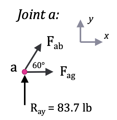
[latex]\sum F_y=0\\R_{ay}+F_{ab}sin(60^\circ) = 0\\F_{ab}=-\frac{R_{ay}}{sin(60^\circ)}=-\frac{83.3 \text{ lb}}{ 0.866} \\\underline{F_{ab} = - 96.2 \text{ lb}} \text{(compression)}[/latex]
[latex]\sum F_x=0\\F_{ag} + F_{ab}cos(60^\circ) = 0 \\F_{ag} =- F_{ab}cos(60^\circ) = - (-96.2 \text{ lb}) * (0.5) \\ \underline{F_{ag} = + 48.1 \text{ lb}} \text{(tension)}[/latex]
Next, move to joint b because you now only have 2 unknowns at joint b (Fbc and Fbg).
Keep analyzing joints until you’ve calculated the load in all members:
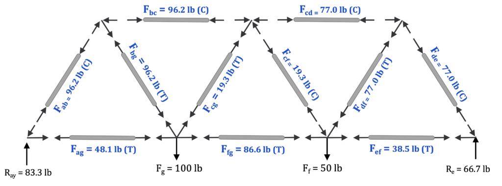
| Member | ab | bc | cd | de | ef | fg | ag | bg |
cg |
cf |
df |
| Force (lb) |
96.2 | 96.2 | 77.0 | 77.0 | 38.5 | 86.6 | 48.1 | 96.2 | 19.3 | 19.3 | 77.0 |
| Tension or Compression |
C | C | C | C | T | T | T | T | T | C | T |
And that’s it! If you don’t specify compression or tension, you should use positive and negative to denote tension and compression, respectively.
Here is a second explanation on how to solve using the method of joints:
The method of joints is a process used to solve for the unknown forces acting on members of a truss. The method centers on the joints or connection points between the members, and it is usually the fastest and easiest way to solve for all the unknown forces in a truss structure.
Using This Method:
The process used in the method of joints is outlined below:
- In the beginning, it is usually useful to label the members and the joints in your truss. This will help you keep everything organized and consistent in later analysis. In this book, the members will be labelled with letters, and the joints will be labelled with numbers.
The first step in the method of joints is to label each joint and each member. - Treating the entire truss structure as a rigid body, draw a free body diagram, write out the equilibrium equations, and solve for the external reacting forces acting on the truss structure. This analysis should not differ from the analysis of a single rigid body.
Treat the entire truss as a rigid body and solve for the reaction forces supporting the truss structure. - Assume there is a pin or some other small amount of material at each of the connection points between the members. Next, you will draw a free-body diagram for each connection point. Remember to include:
- Any external reaction or load forces that may be acting at that joint.
- A normal force for each of the two force members connected to that joint. Remember that for a two-force member, the force will be acting along the line between the two connection points on the member. We will also need to guess if it will be a tensile or a compressive force. An incorrect guess now, though, will simply lead to a negative solution later on. A common strategy then is to assume all forces are tensile, then later in the solution, any positive forces will be tensile forces, and any negative forces will be compressive forces.
- Label each force in the diagram. Include any known magnitudes and directions, and provide variable names for each unknown.
Drawing a free body diagram of each joint, we draw in the known forces as well as tensile forces from each two force member.
- Write out the equilibrium equations for each of the joints. You should treat the joints as particles, so there will be force equations but no moment equations. This should give you a large number of equations.
- The sum of the forces in the x direction will be zero, and the sum of the forces in the y direction will be zero for each of the joints. [latex]\sum\vec F=0\\\sum F_x=0\:\sum F_y=0[/latex]
- Finally, solve the equilibrium equations for the unknowns. You can do this algebraically, solving for one variable at a time, or you can use matrix equations to solve for everything at once. If you assumed that all forces were tensile earlier, remember that negative answers indicate compressive forces in the members.
Source: Engineering Mechanics, Jacob Moore, et al. https://mechanicsmap.psu.edu/websites/5_structures/5-3_method_of_joints/methodofjoints.html
Additional examples from the Mechanics Map – Method of Joints
Example 1:
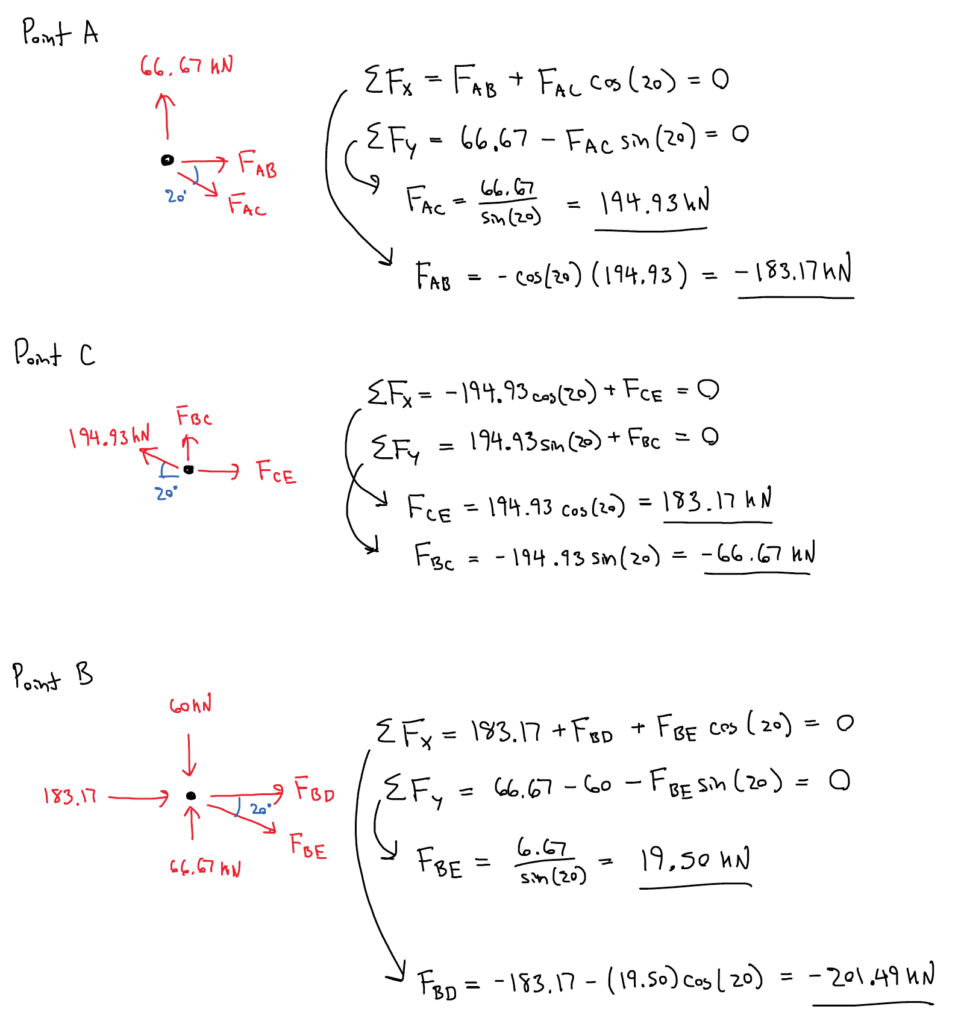
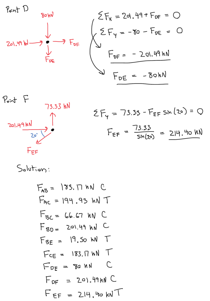
Find the force acting in each of the members in the truss bridge shown below. Remember to specify if each member is in tension or compression.
Solution:
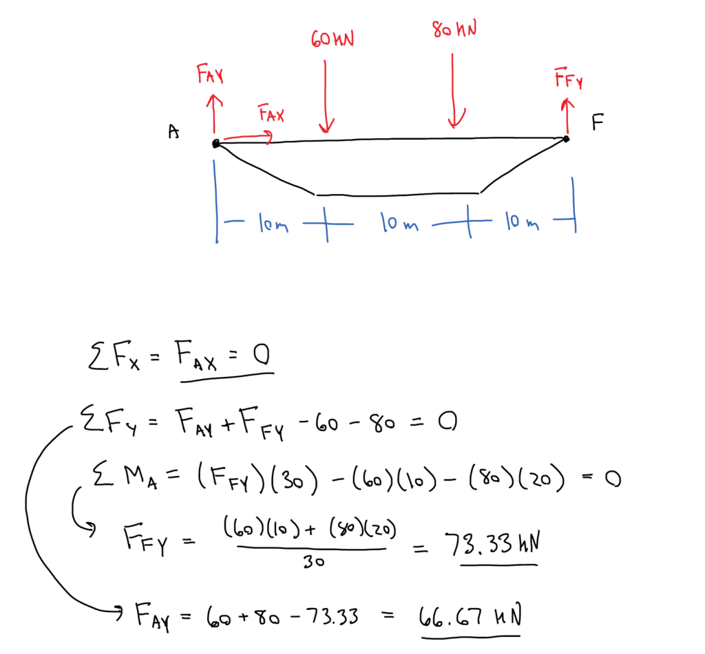
Source: Engineering Mechanics, Jacob Moore, et al. MethodOfJoints_WorkedExample1.pdf
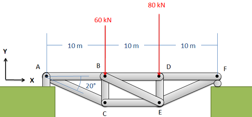
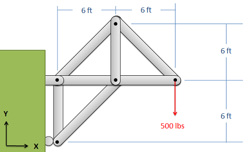
Example 2:
Find the force acting in each of the members of the truss shown below. Remember to specify if each member is in tension or compression.
In summary:
Key Takeaways
Basically: Method of joints is an analysis technique to find the forces in the members of a truss. It looks at each joint individually using the particle equilibrium equations.
Application: To calculate the loads on bridges and roofs, especially if you need to know all of the values of the members.
Looking Ahead: The next section explores a method to solve for one or two members of a truss (instead of finding all of them).
