
Chapter 3: Rigid Body Basics
3.6 Examples
Here are examples from Chapter 3 to help you understand these concepts better. These were taken from the real world and supplied by FSDE students in Summer 2021. If you’d like to submit your own examples, please send them to the author eosgood@upei.ca.
Example 3.6.1: Reaction Forces, Submitted by Andrew Williamson
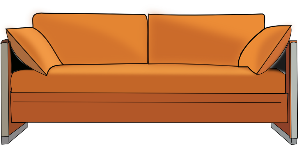
A family is sitting watching TV on their couch. The couch is 5 m long and weighs 120 N. The child is sitting 1 m away from one end and has a mass of 30 kg. The mother is sitting 0.5 m away from the child and has a mass of 60 kg. The father is 3 m away from the mother and has a mass of 70 kg.
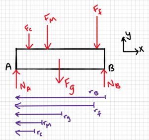
a) Draw a free-body diagram of the couch
b) Calculate the reaction force on each of the two legs.
Assume the couch is supported by two rollers.
2. Draw
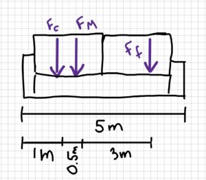
Sketch:
3. Knowns and Unknowns
Knowns:
- g = 9.81 m/s2
- mc = 30 kg
- mm = 60 kg
- mf = 70 kg
- Fg = 120 N
- rc = 1 m
- rM = 1.5 m
- rf = 4.5 m
- rB = 5 m
- rg = 2.5 m
Unknowns:
- NA
- NB
4. Approach
Use equilibrium equations
5. Analysis
Part a:
Part b:
[latex]\sum M_A=0=N_B\times r_B-F_c\times r_c-F_M\times r_M-F_f\times r_f-F_g\times r_g\\\\N_B(5m)=(30kg\times 9.81m/s^2)(1m)+(60kg\times 9.81m/s^2)(1.5m)\\+(70kg\times 9.81m/s^2)(4.5m)+(120N)(2.5m)[/latex][latex]\\N_B(5m)=294.3Nm+882.9Nm +3090.15Nm+300Nm\\\\N_B(5m)=4567.35N m\\\\N_B\frac{4567.35Nm}{5m}\\\\N_B=913.47N\\\\N_B=913N[/latex]
[latex]\sum F_y=0=N_A+N_B-F_C-F_M-F_f-F_g\\\\N_A=F_C+F_M+F_f+F_g-N_B\\\\N_A=(30kg\times 9.81m/s^2)+(60kg\times 9.81m/s^2)\\+(70kg\times 9.81m/s^2)+120N-913.47N[/latex] [latex]\\N_A=294.3N+588.6N+686.7N+120N-913.47N$$$$\\N_A=776.13N\\\\\\\underline{N_A=776N}[/latex]
6. Review
It is interesting that NB is larger than NA, because the weight of the mother and child combined (80 kg) is larger than that of the father (70 kg). However, when you sum the moments at point B instead of A, you get the same answer. The distance between the reaction forces and the nearest forces is important, as well as the magnitude of the forces themselves. The distance between A and Fc is 1 m, while the distance between B and Ff is only 0.5 m.
Additionally, it makes sense that both NA and NB are positive, i.e. are in the positive y direction.
Example 3.6.2: Couples, Submitted by Kirsty MacLellan
1. Problem
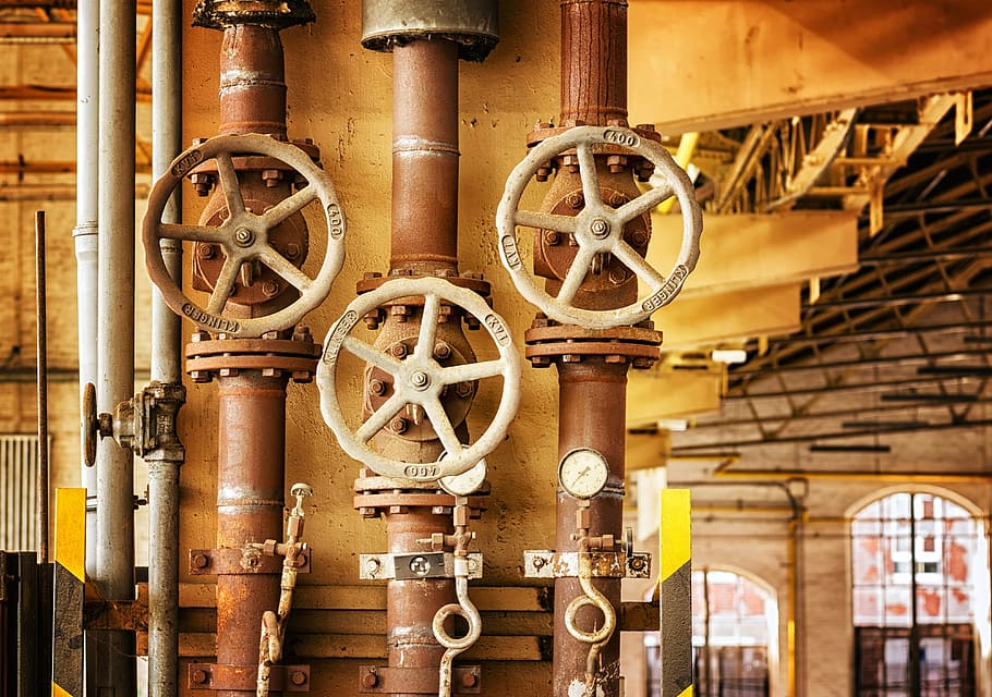
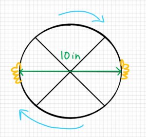
A water valve is opened by a wheel with a diameter of 10 inches. It takes 7.5 lb of force to open the valve. What is the moment it takes to open the valve?
Real-life scenario:
2. Draw
Sketch:
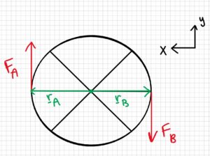
Free-body diagram:
3. Knowns and Unknowns
Known:
- d = 10 in
- F = 7.5 lb
Unknown:
- M
4. Approach
Determine the moment by finding the cross product of rA and FA, then rB and FB, then adding.
5. Analysis
Find radius:
[latex]r=\frac{d}{2}\\r=\frac{10in}{2}\\r=5in\\5in\times\frac{1ft}{12in}=0.42ft[/latex]
Find rA, FA, rB, and FB in vector form:
[latex]\underline{r}_A= \begin{bmatrix} 0.42 \\ 0 \end{bmatrix}ft\:\; \underline{F}_A=\begin{bmatrix} 0 \\ 7.5 \end{bmatrix}lb \\\underline{r}_B=\begin{bmatrix} -0.42 \\ 0 \end{bmatrix}ft\:\; \underline{F}_B=\begin{bmatrix} 0 \\ -7.5 \end{bmatrix}lb[/latex]
Find MA:
[latex]\underline{M}_A=\underline{r}_A\times \underline{F}_A=\begin{bmatrix} \underline{\hat{i}} & \underline{\hat{j}} & \underline{\hat{k}} \\ 0.42 & 0 & 0 \\ 0 & 7.5 & 0 \end{bmatrix}[/latex] [latex]\underline{M}_A=\hat{i} \begin{bmatrix} 0 & 0 \\ 7.5 & 0 \end{bmatrix} -\underline{\hat{j}} \begin{bmatrix} 0.42 & 0 \\ 0 & 0 \end{bmatrix}+\underline{\hat{k}} \begin{bmatrix} 0.42 & 0 \\ 0 & 7.5 \end{bmatrix}\\\underline{M}_A=(\underline{\hat{i}}(0)-\underline{\hat{j}}(0)+\underline{\hat{k}}(0.42\cdot 7.5-0\cdot 0))ft\cdot lb\\\underline{M}_A=3.15\underline{\hat{k}} ft\cdot lb[/latex]
Find MB:
[latex]\underline{M}_B=\underline{r}_B\times \underline{F}_B=\begin{bmatrix} \underline{\hat{i}} & \underline{\hat{j}} & \underline{\hat{k}} \\ -0.42 & 0 & 0 \\ 0 & -7.5 & 0 \end{bmatrix}[/latex] [latex]\underline{M}_B=\hat{i} \begin{bmatrix} 0 & 0 \\ -7.5 & 0 \end{bmatrix} -\underline{\hat{j}} \begin{bmatrix} -0.42 & 0 \\ 0 & 0 \end{bmatrix}+\underline{\hat{k}} \begin{bmatrix} -0.42 & 0 \\ 0 & -7.5 \end{bmatrix}\\\underline{M}_B=(\underline{\hat{i}}(0)-\hat{j}(0)+\underline{\hat{k}}(-0.42\cdot -7.5-0\cdot 0))ft\cdot lb\\\underline{M}_B=3.15\underline{\hat{k}} ft\cdot lb[/latex]
Add MA and MB to get M:
[latex]\underline{M}=\underline{M}_A+\underline{M}_B\\\underline{M}=3.15ft\cdot lb+3.15ft\cdot lb\\\underline{M}=6.3\underline{\hat{k}}ft\cdot lb[/latex]
6. Review
Notice that for the x-coordinates, the positive x-direction was taken to the left, and this was consistently followed in the calculation. It’s important to stay consistent with your chosen direction, as mixing it up can lead to sign errors.
This answer makes sense because there is only one moment acting in the k direction.
Note: We could have come to the same answer using the formula M = F*d, which would have been faster.
[latex]M=f\cdot d\\M=7.5lb\cdot 10in(\frac{1ft}{12in})\\M=7.5lb\cdot \frac{5}{6}ft\\\\M=6.25ft\cdot lb[/latex]
This answer is slightly more accurate because we didn’t round when converting between inches and feet (in the original solution, we rounded 0.416667 to 0.42).
Example 3.6.3: Distributed Load, Submitted by Luciana Davila
1. Problem
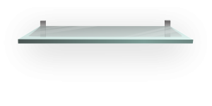
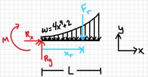
A shelf on the wall is 1.5 meters away from the floor. The shelf has a length of 100 cm. A person starts putting different objects on it to create a distributed load. The load created a curve described by:
w = 4x4 +2 N/m.
Calculate the resultant force and how far it is acting from the wall (Fixed end).
2. Draw
Sketch:
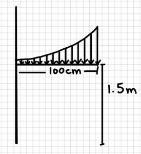
Free-body diagram:
3. Knowns and Unknowns
Knowns:
- w = 4x4 + 2 N/m
- L = 100 cm = 1m
- xmin = 0m
- xmax = 1m
Unknowns:
- xr
- Fr
4. Approach
Use distributed load equations:
[latex]F_r=\int^{xmax}_{xmin} wdx\\X_r=\frac{\int^{xmax}_{xmin} x*w(x)*dx}{\int^{xmax}_{xmin}wdx}[/latex]
5. Analysis
Solve for Fr:
[latex]F_r=\int^1_0 (4x^4+2)dx\;\; N\\F_r=(\frac{4x^5}{5}+2x)\vert^1_0\;\;N\\F_r=(\frac{4}{5}+2)N\\F_r=2.8N[/latex]
Solve for xr:
[latex]X_r=\frac{(\int^1_0x(4x^4+2)dx)N/m}{\int^1_0(4x^4+2)dx)N}\\X_r=\frac{\int^1_0(4x^5+2x)dxN/m}{2.8N}\\X_r=\frac{(\frac{4x^6}{6}+\frac{2x^2}{2})\vert^1_0N/m}{2.8N}\\X_r=\frac{(\frac{2}{3}+1)N/m}{2.8N}\\X_r=0.59m[/latex]
6. Review
The function shows an increasing curve on the interval, so it makes sense that the resultant force would be applied closer to the right end of the beam than the left end.
Example 3.6.4: Couple, Submitted by Hamza Ben Driouech
- Problem
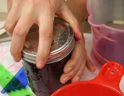
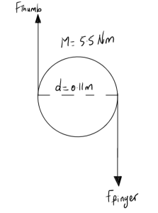
A mason jar lid with a diameter of 11cm is firmly closed and requires a moment of 5.5 Nm to be opened. If you are to open the lid with your finger and thumb, assuming they are applying equal force, determine the force required by your thumb and finger.
2. Draw
3. Knowns and Unknowns
Knowns:
- M = 5.5 Nm
- d = 11 cm = 0.11 m
Unknowns:
- F – Force exerted by thumb and finger
4. Approach
Using couple to find F
5. Analysis
Since the forces exerted by the finger and thumb are equal and opposite, it is possible to find the force exerted by the finger and thumb using the couple equation.
[latex]5.5Nm=F\times0.11m[/latex]
[latex]F=\frac{5.5Nm}{0.11m}\\F =50N[/latex]
Thus, your thumb and finger are applying a force of 50N each.
6. Review
The moment equation is applicable since the force of the thumb and finger is equal. The equation produces a reasonable value of 50N
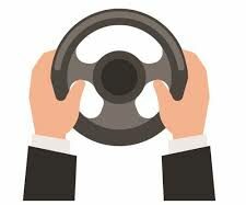
Example 3.6.5: Couple, Submitted by Andrew Williamson.
- Problem
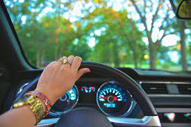
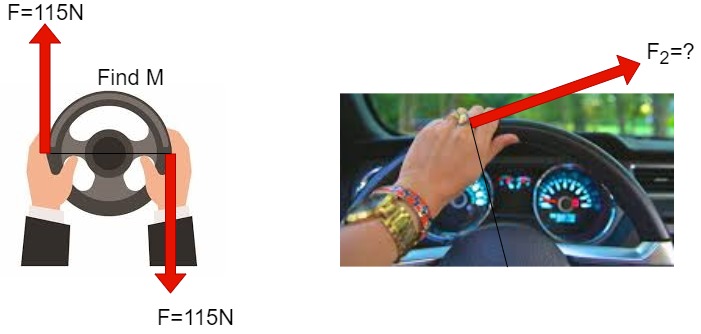
You are driving home from work, and you need to turn right to get into your driveway. To turn the steering, you are applying 115 N with each hand. Consider your steering wheel has a diameter of 40 cm.
a. Determine the couple moment produced on the steering wheel.
b. Compare the above result with a situation where you use single hand to navigate the wheel. How much force does it take to turn the steering wheel in this case?
2. Draw
3. Knowns and Unknowns
Knowns:
- F = 115 N
- d = 40 cm = 0.40m
Unknowns:
- Couple moment, M
- Force applied by hand in the second scenario, F2
4. Approach
Use the couple Moment equation to find the moment, and then use the moment to find the force required to turn the handle single-handedly.
5. Analysis
a. Both arms are applying a 115 N force each. The diameter of the wheel is 40 cm.
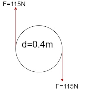
Therefore,
[latex]\overrightarrow{M}= \overrightarrow{F}\times\overrightarrow{d}=115N\times0.4m[/latex]
[latex]\overrightarrow{M}=46Nm[/latex]
b. Consider 46Nm as the required moment to turn the steering wheel.
When just one hand applies force on the wheel it forms a moment which is equal to 46 Nm, with distance and angle given we can find the force it takes to turn the steering wheel.
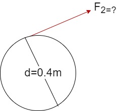
[latex]\overrightarrow{M} = F_{2}\times\frac{d}{2}\times\sin{\theta}\\46Nm =F_{2}\cdot\frac{0.4m}{2}\cdot\sin{90}\\F_{2}=230 N[/latex]
6. Review
As expected, the force it took to turn the steering wheel is twice the force it took with one hand when both hands are used.
Example 3.6.6: Couple, Submitted by Elliot Fraser
- Problem
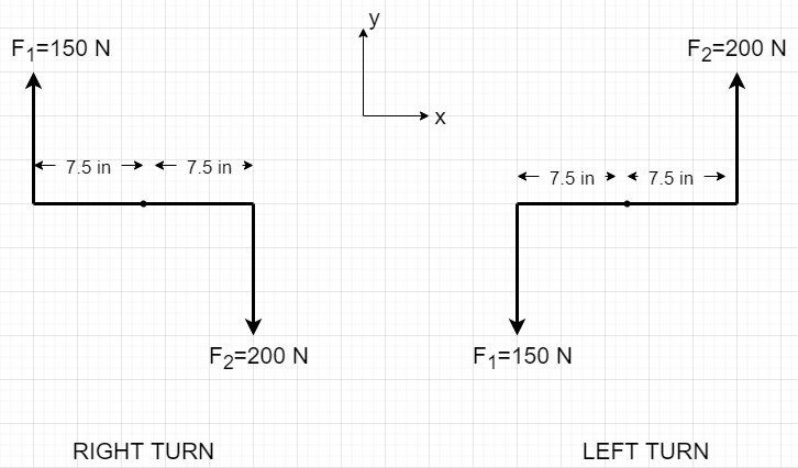
Ellen is taking her driving test and is asked to perform a right turn. The diameter of the steering wheel is 15 inches. Ellen’s right hand exerts a force of 200 N, and her left exerts 150 N.
a. Calculate the net moment in the above-given situation using the cross product.
b. If Ellen were to perform a left turn with the same forces given, what would be the net moment?
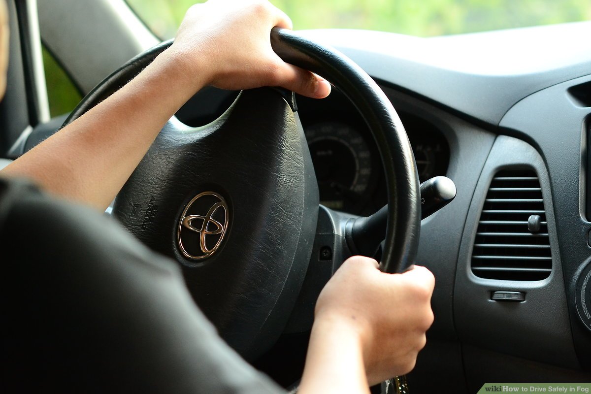
The above image is a close illustration of the problem. In the problem, the hands of the driver are along the diameter.
2. Draw
3. Knowns and Unknowns
Knowns:
- Diameter of the wheel = 15 in = 0.381m
- Right hand force = 200 N
- left hand force = 150 N
Unknowns:
- M1 (for right hand)
- M2 (for left hand)
4. Approach
Convert inches to meters and add the cross product of distance and force to find the net moment.
5. Analysis
a.RIGHT TURN
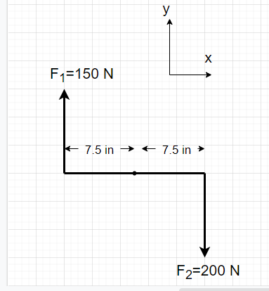
Express the radius of the steering wheel and forces in vector form for tight turn.
[latex]\overrightarrow {r_{1}} = \begin{bmatrix}-0.1905\\0\\0\end{bmatrix}\kern 1pc\overrightarrow {r_{2}} = \begin{bmatrix}0.1905\\0\\0\end{bmatrix}[/latex]
[latex]\overrightarrow {F_{1}} = \begin{bmatrix}0\\150\\0\end{bmatrix}\kern 1pc\overrightarrow {F_{2}} = \begin{bmatrix}0\\-200\\0\end{bmatrix}[/latex]
[latex]\overrightarrow{M_1}=\overrightarrow{r_{1}} \times \overrightarrow{F_{1}} \kern 1pc + \kern 1pc\overrightarrow{r_{2}} \times \overrightarrow{F_{2}}[/latex]
[latex]\overrightarrow{M_{1}}=\:\begin{vmatrix} \hat{i} & \hat{j} & \hat{k} \\-0.1905 & 0 & 0\\0 & 150 & 0\end{vmatrix}[/latex][latex]\kern 1pc + \kern 1pc \begin{vmatrix} \hat{i} & \hat{j} & \hat{k} \\0.1905 & 0 & 0\\0 & -200 & 0\end{vmatrix}[/latex][latex]\:=-28.575\: \hat{k} - 38.1 \hat{k}[/latex]
[latex]\overrightarrow{M_{1}}=\: -66.675 \: \hat{k}[/latex]
b. LEFT TURN
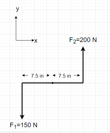
Radius and force in vector form
Radius is the same as it is for a right turn, but the forces have a different direction.
[latex]\overrightarrow {r_{1}} = \begin{bmatrix}-0.1905\\0\\0\end{bmatrix}\kern 1pc\overrightarrow {r_{2}} = \begin{bmatrix}0.1905\\0\\0\end{bmatrix}[/latex]
[latex]\overrightarrow {F_{3}} = \begin{bmatrix}0\\-150\\0\end{bmatrix}\kern 1pc\overrightarrow {F_{4}} = \begin{bmatrix}0\\200\\0\end{bmatrix}[/latex]
[latex]\overrightarrow{M_2}=\overrightarrow{r_{1}} \times \overrightarrow{F_{3}} \kern 1pc + \kern 1pc\overrightarrow{r_{2}} \times \overrightarrow{F_{4}}[/latex]
[latex]\overrightarrow{M_{2}}=\:\begin{vmatrix} \hat{i} & \hat{j} & \hat{k} \\-0.1905 & 0 & 0\\0 & -150 & 0\end{vmatrix}[/latex][latex]\kern 1pc + \kern 1pc \begin{vmatrix} \hat{i} & \hat{j} & \hat{k} \\0.1905 & 0 & 0\\0 & 200 & 0\end{vmatrix}[/latex][latex]\:=28.575\: \hat{k} + 38.1 \hat{k}[/latex]
[latex]\overrightarrow{M_{2}}=\: 66.675 \: \hat{k}[/latex]
6. Review
Because the radius and force values in both instances have the same magnitude but different directions, the net moments for left and right turns were expected to have the same magnitudes and different directions; thus, the answers make sense.
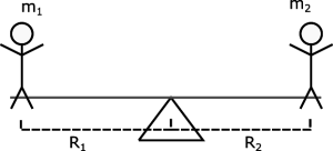
Example 3.6.7: Lever Arms, Submitted by Dhruvil Kanani
1. Problem
build a Seesaw (tatter-totter) for his sons in a way that both the kids have to apply an equal amount
of force. What is the required ratio of the lengths of both arms to achieve this? Acceleration due to gravity is 9.81m/s2.
2. Sketch:
3. Knowns and Unknowns:
Knowns:
- m1 = 35kg
- m2 = 50kg
- g = 9.81 m/s2
Unknown:
- R1
- R2
4. Approach:
Convert the masses to forces using gravity.
Equate the moments caused by each force.
Solve for the ratio of lengths.
5. Analysis:
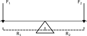
For the children to apply an equal amount of force while playing on the seesaw, they must create an equal moment.
Therefore:
[latex]M_1 = M_2[/latex]
These moments can be rewritten in terms of F and R.
[latex]F_1 \cdot R_1 = F_2 \cdot R_2[/latex]
The F values can be solved by multiplying the child’s mass by gravity to find the force they exert on the seesaw.
[latex](m_1 \cdot g) \cdot R_1 = (m_2 \cdot g) \cdot R_2[/latex]
Gravity can be cancelled out as it exists on both sides of the equation, leaving:
[latex]m_1 \cdot R_1 = m_2 \cdot R_2[/latex]
Putting values into this equation gives:
[latex]35kg \cdot R_1 = 50kg \cdot R_2[/latex]
The equation can now be adjusted to solve for R1/R2.
[latex]\frac{R_1}{R_2} = \frac{50kg}{35kg}[/latex]
This can be simplified to give the ratio:
[latex]\frac{R_1}{R_2} = \frac{10}{7} \\ R_1 : R_2 = 10 : 7[/latex]
6. Review
It makes sense that the lighter child needs to be further away to produce an equal moment to that of the heavier child. 10:7 is a reasonable ratio that matches the ratio of their weights.
Example 3.6.8: Distributed loads, Submitted by Will Craine
1. Problem
There are 5 cars on a bridge, three in one lane and the rest in the second lane. Each car is of identical dimensions and weight.
a. Find the resultant force of the cars from the side of the bridge with 3 cars.
b. Find the resultant force of the cars from the side of the bridge, with 2 cars in the opposite direction to the other 3 cars.
c. Find the resultant force of all 5 cars and the location of this force using the average of the x and y coordinates.
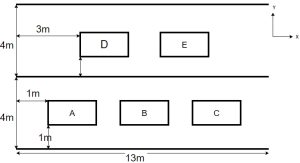 Figure 1: Top view of the bridge
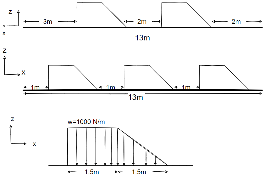
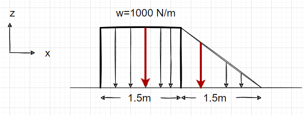
Figure 2: Drawing denoting direction and dimension of cars and bridge (Assuming the cars are in a Trapezium Shape).
2. Draw
3. Knowns and Unknowns
Knowns:
- Dimensions of the cars and the bridge
- Weight of one car, w = 1000 N/m
Unknowns:
- The resultant force on either side of the bridge.
- The location of the resultant force of all 5 cars.
4. Approach
- The weight of the cars is distributed along the dimensions. We figure out he resultant forces and the location of the resultant forces along the x direction using the equation [latex]\bar{x}=\frac{\sum F_{i}x_i}{\sum F_i}[/latex].
- Note that the shape of the car consists of a rectangle and an adjacent triangle. Hence, the distributed load is found for both shapes, using equations appropriate to find the area under the force, and then added to form the resultant force of one car.
5. Analysis
a. Finding the location along the x-axis and the magnitude of the resultant force of 3 cars
Since all 3 cars are identical [latex]F_{A}=F_{B}=F_{C}[/latex].
From the fig above
[latex]F_{R1}=1000 N/m \times 1.5 m = 1500 N[/latex]
[latex]F_{R2} = \frac{1}{2} \times 1.5 m \times 1000 N/m = 750 N[/latex]
[latex]F_{A} = 1500 N + 750 N = 2250N[/latex]
[latex]\bar {x}[/latex] for resultant force of car A
From O [latex]F_{R1}[/latex] locates at [latex]1+ \frac{1}{2}(1.5) = 1.75 m[/latex]
[latex]F_{R2}[/latex] locates at [latex]1+ 1.5+ \frac{1}{3}(1.5) = 3 m[/latex]
now, [latex]\bar{x}=\frac{\sum F_{i}x_i}{\sum F_i}[/latex]
thus [latex]\bar{x_{A}}= \frac {(1500 N/m\times 1.75m+(750 N/m\times 3m)}{(1500N +750N)}[/latex]
[latex]\bar{x_{A}} = 2.17 m[/latex] from left side.
Also for one car the [latex]\bar{x}[/latex] of 2250 N force is [latex]2.17m - 1 m = 1.17 m[/latex]
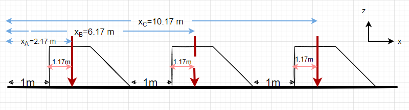
Using these calculations, the following figure can be drawn.
The total resultant force of all 3 cars is [latex]F_{R3} = 2250N \times 3 = 6750 N[/latex]
[latex]\bar{x}=\frac{\sum F_{i}x_i}{\sum F_i}[/latex]
therefore,
[latex]\bar{x} = \frac{(2.17 \times 2250)+(6.17\times 2250)+(10.17\times 2250)}{6750}[/latex]
[latex]\bar{x} = 6.17 m[/latex] from left side .
b. Position and magnitude of the resultant force of the 2 cars on the lane.
[latex]F_{D} = F_{E}=2250 N[/latex]
Total force of the 2 cars [latex]F_{R2} = 2250 \times 2= 4500 N[/latex]
Position of the resultant forces from the 2 cars,
[latex]\bar {x_{2}} = \frac {(4.17 \times 2250) + (9.17 \times 2250)}{4500}=6.67 m[/latex]
6.67 m is from the right side, but from the left side [latex]\bar{x_{2}} = 13-6.67 = 6.33 m[/latex]
c. Position and magnitude of the total resultant force on the bridge.
Total force on bridge due to the 5 cars [latex]F_{R5} =F_{R2} +F_{R3} = 4500 N + 6750 N = 11250 N[/latex]
[latex]\bar{x} = \frac{(F_{R2}\times \bar{x_{2}})+(F_{R3}\times\bar{x_{3}})}{F_{R5}}[/latex]
[latex]\bar {x} =\frac{ (6.33 \times 4500)+ (6.17 \times 6750 )}{11250}= 6.234 m[/latex]
[latex]\bar {y} [/latex] for all the cars is half of its width
therefore, [latex]\bar{y_{5}} = \frac{(\bar{y_{2}}\times F_{R3} )+(\bar{}y_{3}\ times F_{R3})}{F_{R5}}[/latex]
[latex]\bar{y_{5}} = \frac{(6m \times 4500 N )+(2m \times 6750 N)}{11250 N}[/latex]
[latex]\bar{y_{5}} = 3.6 m[/latex]
[latex]F_{R5} = 11250 N \quad at \quad (6.234m , 3.6 m )[/latex]
6. Review
This problem is less complex because of the symmetry of the cars and the bridge. The coordinates of the resultant force are just as expected. x is closer to the side with more weight (due to the distribution of weight of the vehicles), and y is less than halfway across the bridge because that side has more vehicles
Example 3.6.9: Couple, Submitted by Anonymous
1. Problem
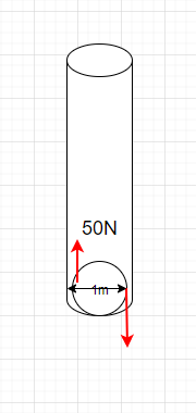
A boy is trying to close a round-shaped water tap of diameter 1 m with a force of F = 50 N on both sides of the cylinder. Determine the couple moment produced.
2. Draw
3. Known and Unknowns
Knowns:
- F =50 N
- Diameter, d = 1m
Unknown:
- Couple moments, M
4. Approach
Using Equation [latex]M = F\times d[/latex]
5. Analysis
Couple moment, [latex]M = F\times d = 50N \times 1 m= 50 Nm [/latex]
6. Review
Note that in this question, the direction of the rotation of the tap is not mentioned. But the sign of the couple moment changes with respect to the direction of rotation and the coordinates which you choose to be positive.
