
Chapter 3: Rigid Body Basics
3.1 Right Hand Rule
Before we can analyze rigid bodies, we need to learn a little trick to help us with the cross product called the ‘right-hand rule’. We use the right-hand rule when we have two of the axes and need to find the direction of the third.
-
-
- [latex]\underline{\hat{i}}\times\underline{\hat{j}}=\underline{\hat{k}}[/latex]
- [latex]\underline{\hat{j}}\times\underline{\hat{k}}=\underline{\hat{i}}[/latex]
- [latex]\underline{\hat{k}}\times\underline{\hat{i}}=\underline{\hat{j}}[/latex]
- [latex]\underline{\hat{j}}\times\underline{\hat{i}}=-\underline{\hat{k}}[/latex]
- [latex]\underline{\hat{k}}\times\underline{\hat{j}}=-\underline{\hat{i}}[/latex]
- [latex]\underline{\hat{i}}\times\underline{\hat{k}}=-\underline{\hat{j}}[/latex]
-
The opposite of the right-orthogonal system is the left-orthogonal system where [latex]\underline{\hat{i}}\times\underline{\hat{j}}=-\underline{\hat{k}}[/latex]. We don’t use that one!
There are two ways to do the right hand rule, and they take practice to conceptually understand, but this will make solving problems much quicker. You’re going to use your fingers and thumb to represent the x, y, and z axes.
3.1.1 The Whole-Hand Method
The direction of the cross product vector A x B is given by the right-hand rule for the cross product of two vectors. To apply this right-hand rule, extend the fingers of your right hand so that they are pointing directly away from your right elbow. Extend your thumb so that it is at
right angles to your fingers.
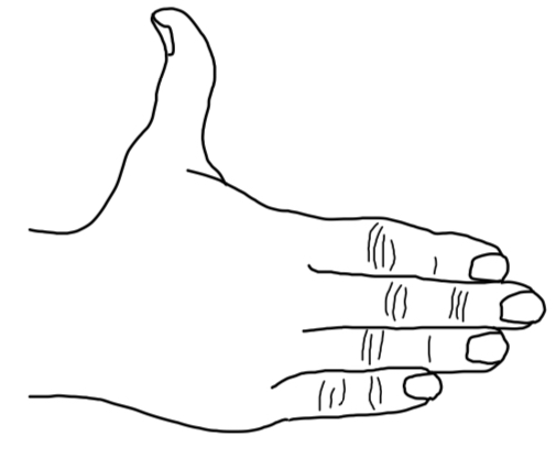
Keeping your fingers aligned with your forearm, point your fingers in the direction of the first vector (the one that appears before the “×” in the mathematical expression for the cross product; e.g. the A in A x B ).
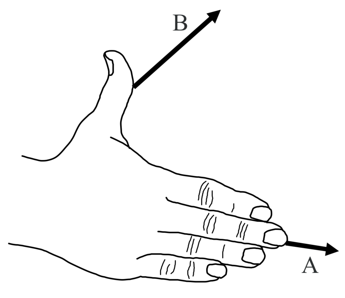
Now rotate your hand, as necessary, about an imaginary axis extending along your forearm and along your middle finger, until your hand is oriented such that, if you were to close your fingers, they would point in the direction of the second vector.
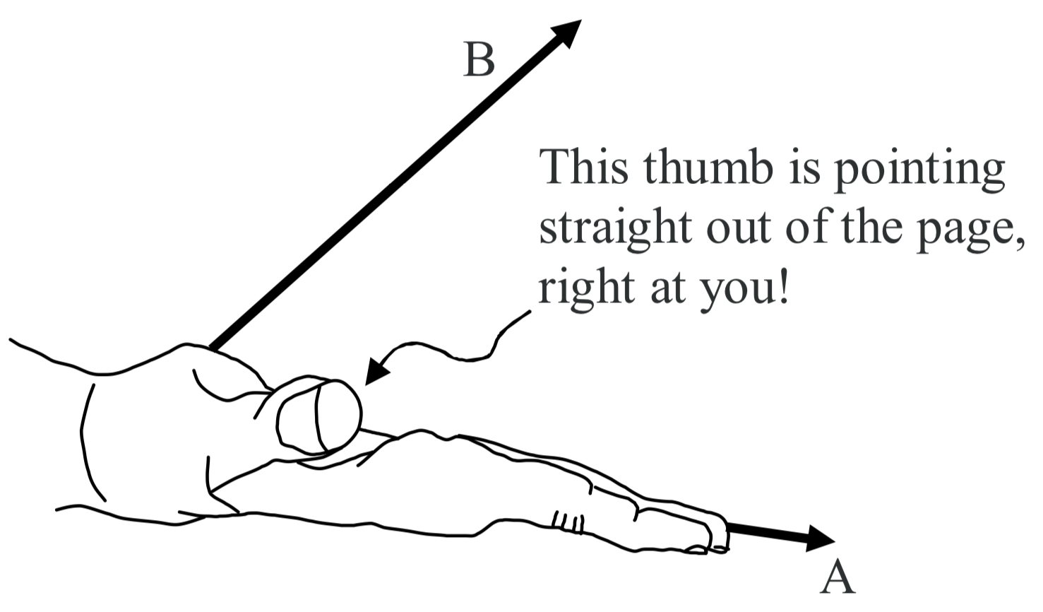
Your thumb is now pointing in the direction of the cross product vector. C = A x B. The cross product vector C is always perpendicular to both of the vectors that are in the cross product (the A and the B in the case at hand). Hence, if you draw them so that both of the vectors that are in the cross product are in the plane of the page, the cross product vector will always be perpendicular to the page, either straight into the page, or straight out of the page. In the case at hand, it is straight out of the page.
When we use the cross product to calculate the torque due to a force F whose point of application has a position vector r, relative to the point about which we are calculating the torque, we get an axial torque vector τ. To determine the sense of rotation that such a torque vector would correspond to, about the axis defined by the torque vector itself, we use the Right Hand Rule for Something Curly Something Straight. Note that we are calculating the torque with respect to a point rather than an axis—the axis about which the torque acts comes out in the answer.
Source: Jeffrey W. Schnick https://openlibrary.ecampusontario.ca/catalogue/item/?id=ce74a181-ccde-491c-848d-05489ed182e7 pages 135–137
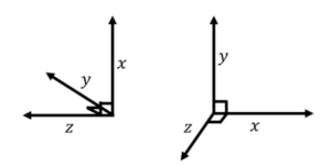
The hardest part of the right-hand rule is imagining the different axes and envisioning how they are perpendicular to each other. 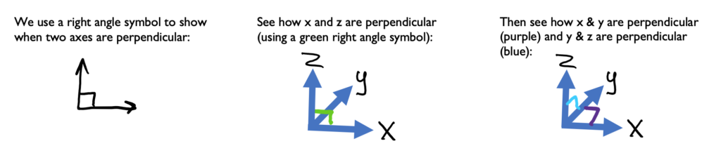
Try this one in 2d and 3d. Imagine (or draw) the right-angle symbols (Answer will be in a few steps)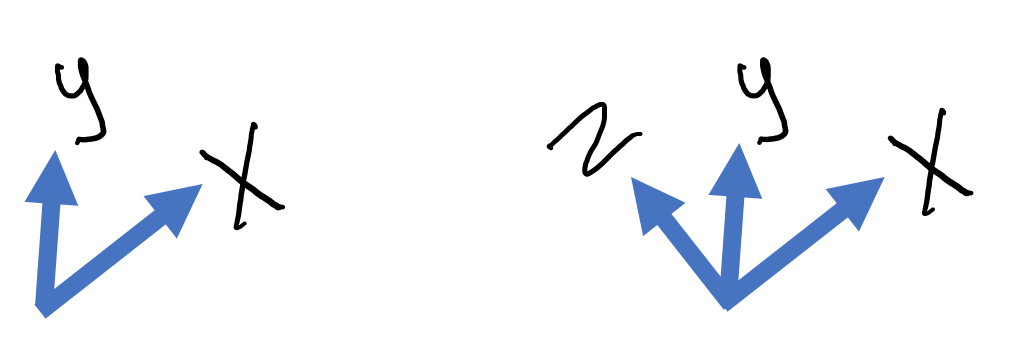
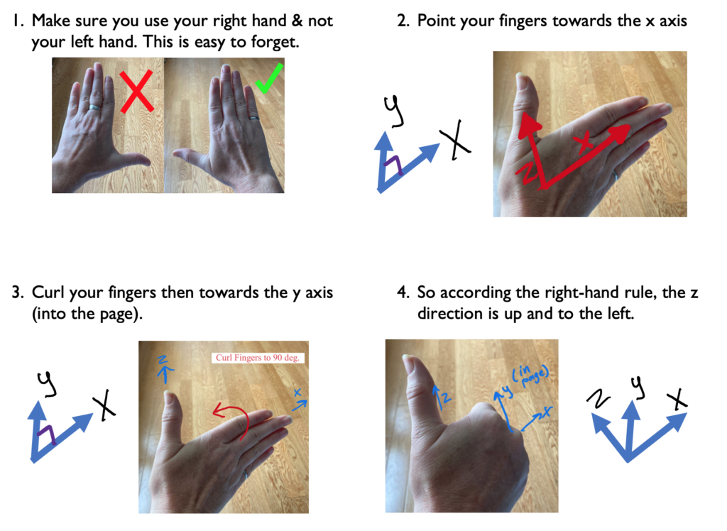
Example 1:
Using these x and y, let’s use the right-hand rule to find the direction of z.
Here are the steps you can follow:
Example 2:
Sometimes you will need to flip your hand 180 degrees to find which way lets you point your fingers in the y direction, for example:
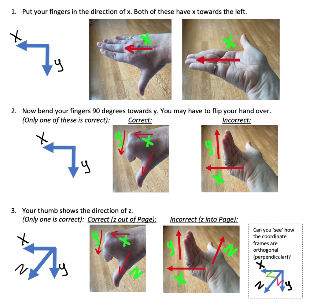
Example 3:
It’s important for you to be able to envision how the axes are perpendicular. Now practice using the right hand rule if you are trying to find x.
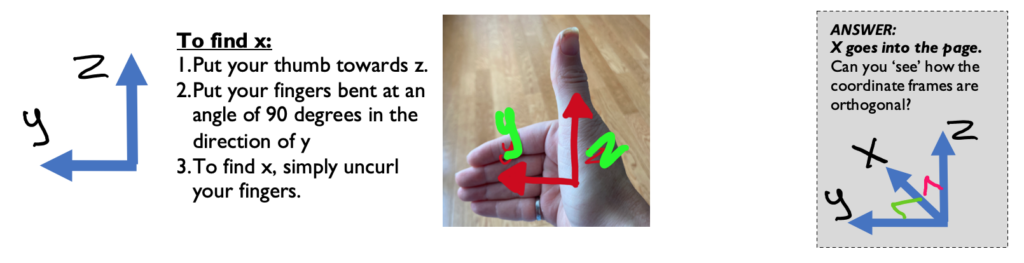
Your Turn!
Keep going with these examples. The rules stay the same: thumb towards z, curled fingers towards y, extended fingers towards x. Find the missing axis: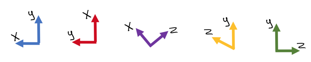
.
.
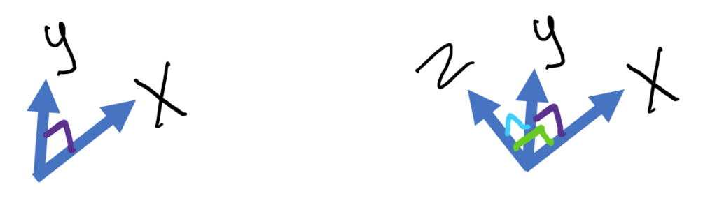
Did you do it?
.
.
.
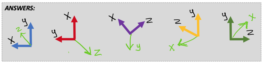
Here are the answers:
.
.
3.1.2 Right Hand Rule and Torque
The third way to calculate torque, as was alluded to in Section 1.6, is to use the right-hand rule to identify the axis of rotation. The first way (the scalar method) uses | M | = |r| |F| sin Θ, and often the angle between the position vector and force is 90 degrees. The vector method is for more complicated situations and uses the cross product r x F = M. The third method finds the scalar value separately, then uses the right-hand rule to find the direction (positive or negative along the third axis).
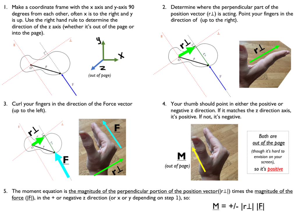
- Point your fingers in the direction of the perpendicular part of the position vector r (as you would for x)
- Curl them towards the direction of the Force vector F (as you would for y)
- Your thumb is in the direction of the moment M that results from the force (as for z)
The following will help you understand what is meant by: the perpendicular part of the position vector:
The torque τ can be expressed as the cross product of the position vector r for the point of application of the force, and the force vector F itself: r x F = M
Before we begin our mathematical discussion of what we mean by the cross product, a few words about the vector r are in order. It is important for you to be able to distinguish between the position vector r for the force, and the moment arm, so we present them below in one and the same diagram. We use the same example that we have used before: 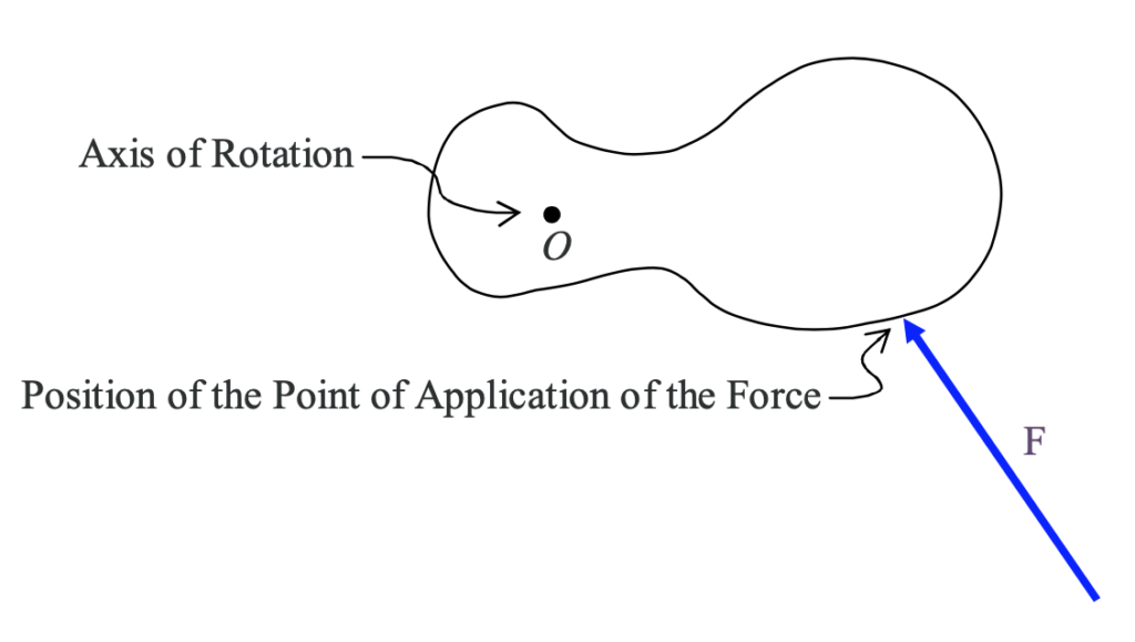
in which we are looking directly along the axis of rotation (so it looks like a dot) and the force lies in a plane perpendicular to that axis of rotation. We use the diagramatic convention that, the point at which the force is applied to the rigid body is the point at which one end of the arrow in the diagram touches the rigid body. Now we add the line of action of the force and the moment arm r⊥ to the diagram, as well as the position vector r of the point of application of the force. 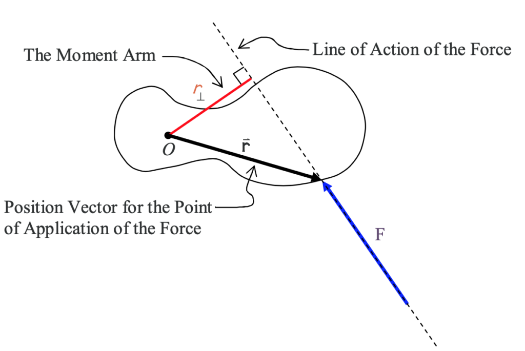
The moment arm can actually be defined in terms of the position vector for the point of application of the force. Consider a tilted x-y coordinate system, having an origin on the axis of rotation, with one axis parallel to the line of action of the force and one axis perpendicular to the line of action of the force. We label the x axis ┴ for “perpendicular” and the y axis || for “parallel”.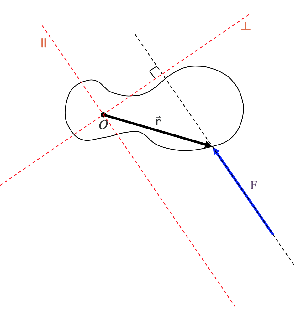
Now we break up the position vector r into its component vectors along the ┴ (perpendicular) and || (parallel) axes.
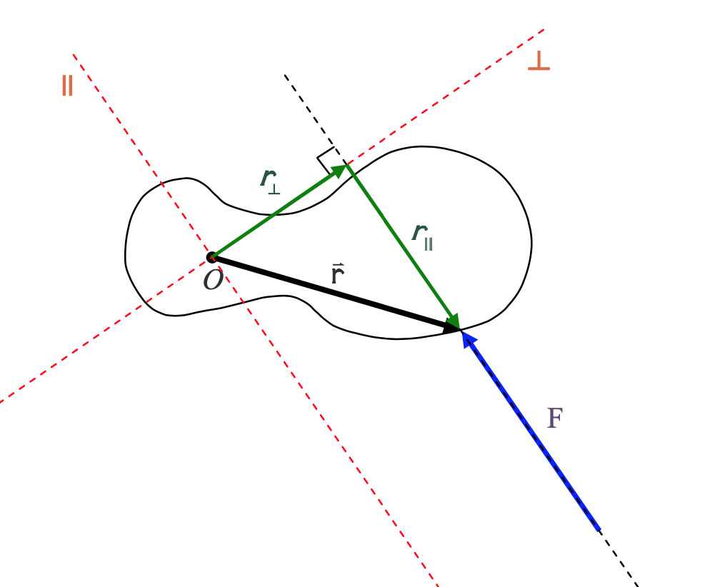
From the diagram it is clear that the moment arm r is just the magnitude of the component ┴ vector, in the perpendicular-to-the-force direction, of the position vector of the point of application of the force.
You use the right-hand rule twice during this method to find the vector. First, to determine the coordinate frame and again to see in which direction the torque is aligned. Then you multiply by the magnitude of the perpendicular portion of the position vector (r⊥ or the “moment arm”) and the magnitude of the force vector. ):
|M| = +/- |r⊥| |F| [latex]\hat{\underline{k}}[/latex]
* though it’s not always the [latex]\hat{\underline{k}}[/latex] direction, it could be [latex]\hat{\underline{i}}[/latex] or [latex]\hat{\underline{j}}[/latex] as well. It depends on how you define your coordinate frame.
Example 4:
3.1.3 Three-Finger Configuration
If you find curling your fingers too confusing, you can try this method that uses your thumb, pointer finger, and middle finger all 90 degrees apart. Your thumb is x, your pointer finger is y, your middle finger is z.
This is done by using your right hand, aligning your thumb with the first vector and your index with the second vector. The cross product will point in the direction of your middle finger (when you hold your middle finger perpendicular to the other two fingers). This is illustrated in the Figures below. 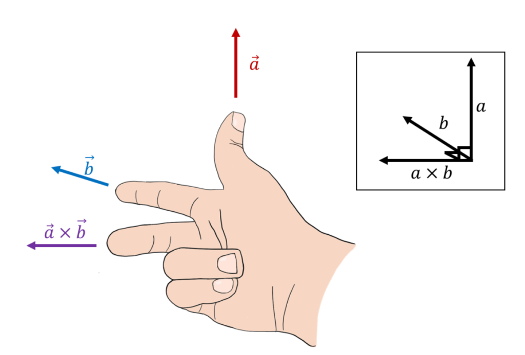
Source: Introductory Physics, Ryan Martin et al.,https://openlibrary.ecampusontario.ca/catalogue/item/?id=4c3c2c75-0029-4c9e-967f-41f178bebbbb, pages 823–825
The “Curly Method”
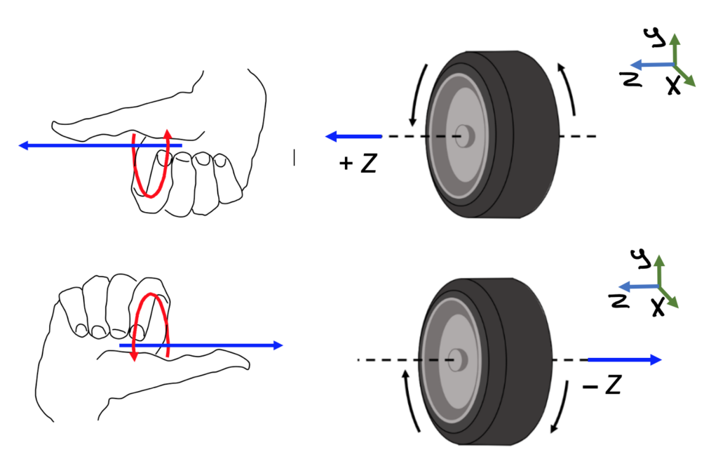
For axial vectors, you use what I’m calling the curly method. To find whether the axis of rotation is positive or negative, curl your fingers in the direction of rotation and your thumb shows the direction of rotation, i.e. whether rotation is along the positive or negative x y or z direction. (This assumes you already have a coordinate frame defined to see which axis the wheel is rotating around and which direction).
If a wheel is rolling, the axis is what it rolls around. Curl your fingers in the direction of rotation and your thumb shows the direction of rotation.[1]
Key Takeaways
Basically: The right hand rule helps us to be consistent with how the x – y – z axes are oriented. It follows the rule that X x Y = Z. Using your fingers and thumb, there are two different methods. For one point, point your fingers in the direction of x, curl them towards y (you may have to flip your hand), and your thumb shows the direction of z. Trying to copy this 3d image onto your 2d page may be difficult, but with practice, you’ll see the right angles between the drawn axes.
Application: How do I know which way to push on the torque wrench to make the bolt on my wheel turn? If I point my thumb in the direction I want the bolt to move, and curl my fingers around the direction of the threads, I can see whether to push or pull on the wrench.
Looking Ahead: We will calculate the moment many times throughout the rest of the book, and we need the right-hand rule every time, especially as we get into Chapter 4 and Rigid Body Equilibrium Equations.
- Hand from page 127 of Calculus Based Physics, Jeffrey W. Schnick, https://openlibrary.ecampusontario.ca/catalogue/item/?id=ce74a181-ccde-491c-848d-05489ed182e7 & tire from page 828 of Introductory Physics, Ryan Martin et al., https://openlibrary.ecampusontario.ca/catalogue/item/?id=4c3c2c75-0029-4c9e-967f-41f178bebbbb, Edited by author. ↵
