
Chapter 3: Rigid Body Basics
3.4 Reactions & Supports
Imagine a beam extending from the wall. How much weight can the beam handle before it breaks away or falls off the wall? It depends on the way it’s attached to the wall. We model these real-world situations using forces and moments. For example, the Grand Canyon Skywalk lets people walk out over the Grand Canyon. You want to be sure that the skywalk is so that the people on it are safe.

We call the skywalk a cantilever beam and turn the real world beam into a 2d model with constrains. So we can use the same terminology, it is a fixed constraint, preventing horizontal movement, vertical movement, and rotation.
Reaction forces and moments are how we model constraints on structures. They are external forces. There are 3 different kinds of constraints we will focus on in this course and they each have different reaction forces and moments:
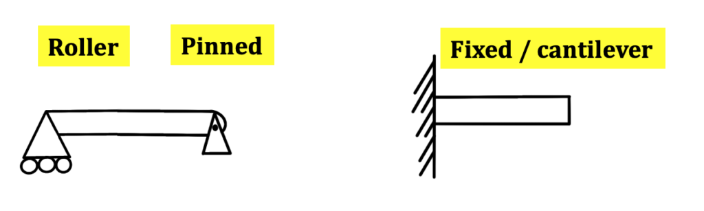
1. Pinned (Frictionless)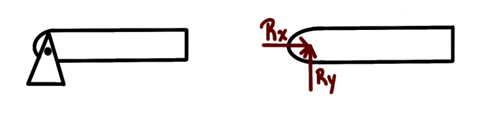
-
- Two reaction forces acting perpendicularly in the x and y directions.
- Pinned constraint and then its free body diagram shown:
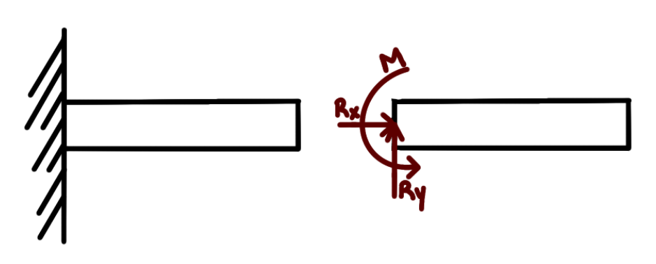
2. Fixed
-
- Two reaction forces acting perpendicularly in the x and y directions
- Moment rotating about fixed constraint (usually a wall), use right hand rule to find its direction
- This is also called a cantilever beam.
- Fixed constraint and then FBD shown
- Two reaction forces acting perpendicularly in the x and y directions
3. Roller (there are multiple kinds)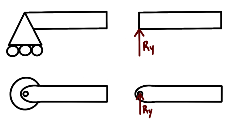
-
- Single reaction force acting in the y direction
- No moment is created
- This can be the ground that the object rests on as well
- Free body diagram shown for roller
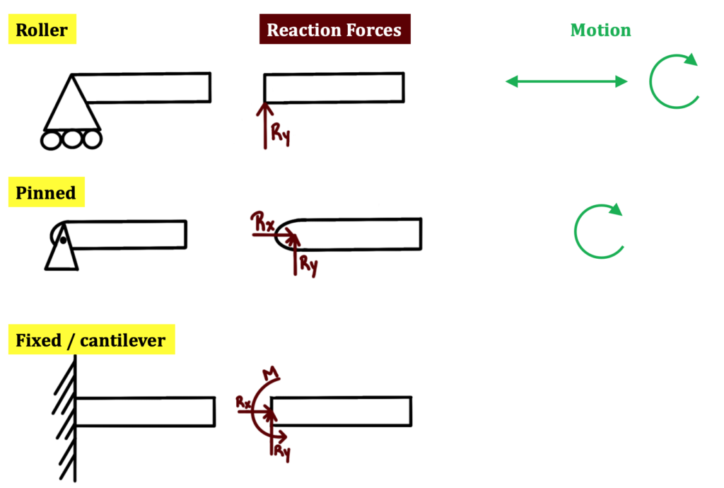
Notice that the Fixed restraint is the most restrictive and the roller is the least restrictive. You put a force to show how the restraint restricts motion. The roller only keeps the object from moving vertically, so there is only 1 force. The pinned restraint doesn’t allow horizontal or vertical movement, hence the two forces. The fixed beam restricts vertical translation, horizontal translation, and rotation, so there is a moment and two forces. Note that this applies only to 2d restraints.
Here is a summary showing what motion is allowed by that type of constraint:
Typically, reaction forces are either as follows: a roller and a pinned reaction force together (1 reaction force + 2 reaction forces = 3 restraints) or a fixed beam (2 reaction forces and 1 moment = 3 restraints).
The information shown here is to model 2d situations. We don’t get into 3d problems in this statics course, needless to say, there are more reaction forces and moments involved in 3-dimentsions instead of 2 dimensions. The following section provides a second explanation on reactions & supports:
3.4.1 Pin or Hinge Support
A pin support allows rotation about any axis but prevents movement in the horizontal and vertical directions. Its idealized representation and reactions are shown in Table 3.1
Table 3.1 Reaction Representations
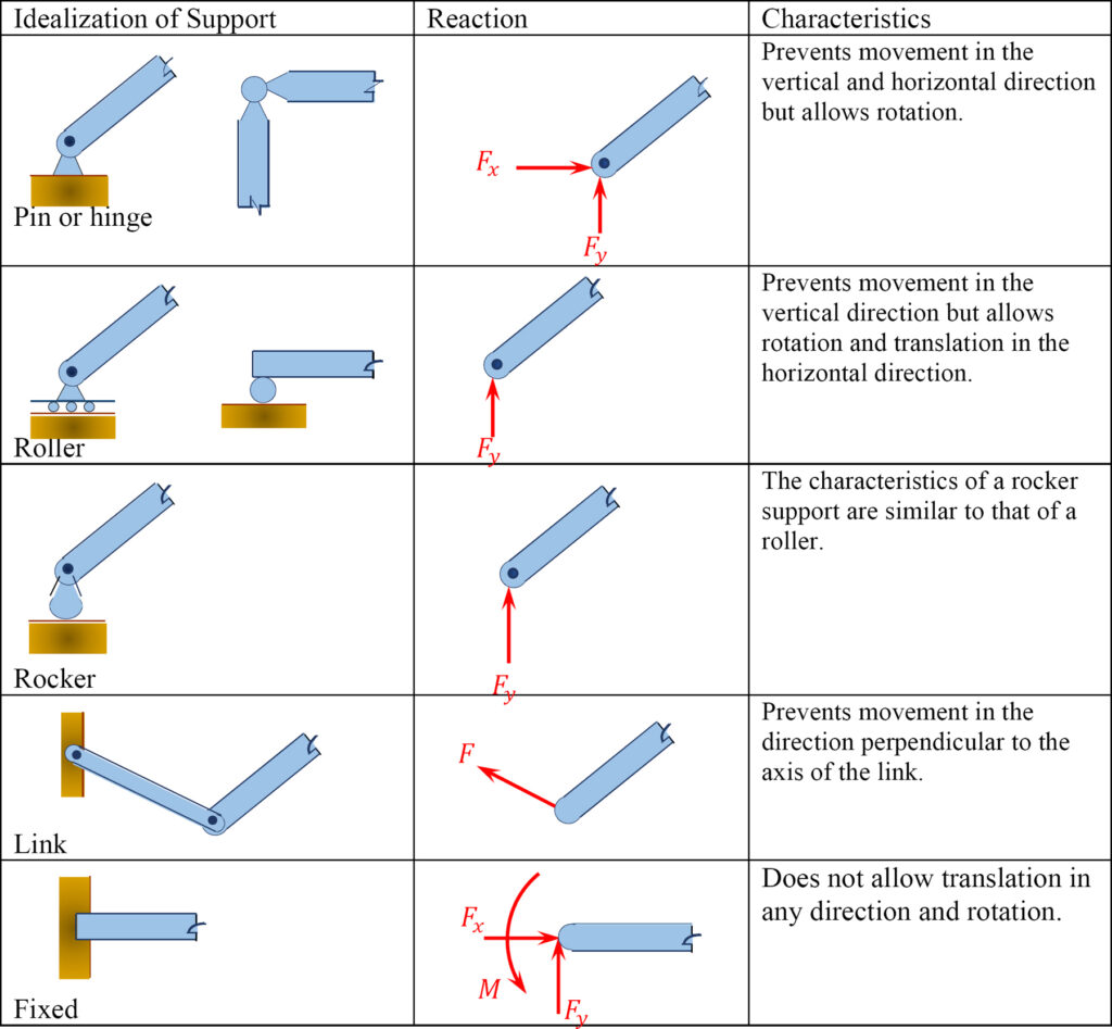
3.4.2 Roller Support
A roller support allows rotation about any axis and translation (horizontal movement) in any direction parallel to the surface on which it rests. It restrains the structure from movement in a vertical direction. The idealized representation of a roller and its reaction are also shown in Table 3.1.
3.4.3 Rocker Support
The characteristics of a rocker support are like those of the roller support. Its idealized form is depicted in Table 3.1.
3.4.4 Link
A link has two hinges, one at each end. It permits movement in all direction, except in a direction parallel to its longitudinal axis, which passes through the two hinges. In other words, the reaction force of a link is in the direction of the link, along its longitudinal axis.
3.4.5 Fixed Support
A fixed support offers a constraint against rotation in any direction, and it prevents movement in both horizontal and vertical directions.
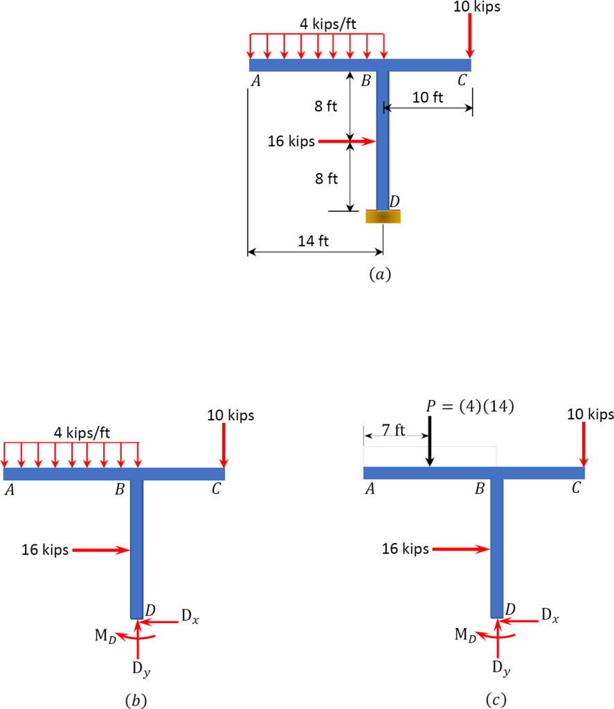
Example 1:
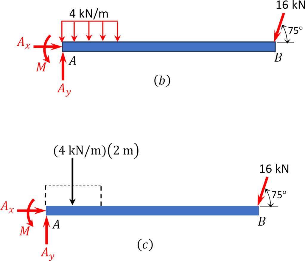
Example 2 (Ax added even though it turns out to be 0):
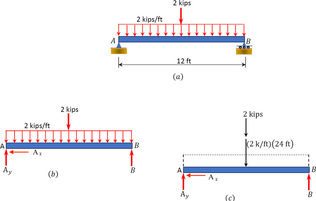
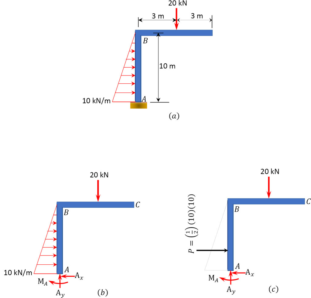
Example 3:
Example 4:
Source: ” Equilibrium Structures, Support Reactions, Determinacy and Stability of Beams and Frames” by LibreTexts is licensed under CC BY-NC-ND . https://eng.libretexts.org/Bookshelves/Civil_Engineering/Book%3A_Structural_Analysis_(Udoeyo)/01%3A_Chapters/1.03%3A_Equilibrium_Structures_Support_Reactions_Determinacy_and_Stability_of_Beams_and_Frames
Key Takeaways
Basically: Reaction forces and moments (or constraints) show how motion is restricted, here that is in 2 dimensions.
Application: A beam attached to the wall has three ways of restricting the motion: horizontal, vertical, and rotational.
Looking Ahead: Every time we model a scenario, we will use reaction forces to show what type of motion is being restrained. In Chapter 4, we will be able to calculate the reaction forces/moments.
Written by Gayla & Libby
