
Chapter 5: Trusses
5.1 Trusses Introduction
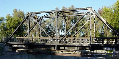
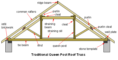
Trusses are rigid structures made up of two-force members, which are objects with exactly two forces/connections. Trusses are commonly found in the frame of a roof and the sides of a bridge:
You’ll analyze these structures more in your Structures course, but for Statics, you will need to know how to calculate the force in each member, using the method of joints and the method of sections. The method of joints is more like a particle analysis, wherein you use only x and y equilibrium equations. The method of sections is more like a rigid body analysis, where you can also include the moment equilibrium equation. Those are in the next sections.
5.1.1 Two Force Members
Before we discuss the structure of trusses, we must begin by defining two force members:
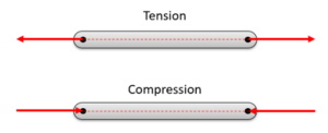
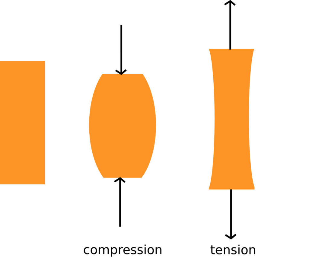
A two-force member is a body that has forces (and only forces, no moments) acting on it in only two locations. In order to have a two-force member in static equilibrium, the net force at each location must be equal, opposite, and collinear. This will result in both force members being in either tension or compression as shown in the diagram below.
Imagine a beam where forces are only exerted at each end of the beam (a two-force member). The body has some non-zero force acting at one end of the beam, which we can draw as a force vector. If this body is in equilibrium, then we know two things: 1) the sum of the forces must be equal to zero, and 2) the sum of the moments must be equal to zero.
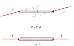
In order to have the sum of the forces equal to zero, the force vector on the other side of the beam must be equal in magnitude and opposite in direction. This is the only way to ensure that the sum of the forces is equal to zero with only two forces.
In order to have the sum of the moments equal to zero, the forces must be collinear. If the forces were not collinear, then the two equal and opposite forces would form a couple. This couple would exert a moment on the beam when there are no other moments to counteract the couple. Because the moment exerted by the two forces must be equal to zero, the perpendicular distance between the forces (d) must be equal to zero. The only way to achieve this is to have the forces be collinear.
Source: Engineering Mechanics, Jacob Moore, et al. http://mechanicsmap.psu.edu/websites/5_structures/5-1_structures/structures.html
5.1.2 Trusses
A truss is an engineering structure that is made entirely of two force members. In addition, statically determinate trusses (trusses that can be analyzed completely using the equilibrium equations), must be independently rigid. This means that if the truss was separated from its connection points, no one part would be able to move independently with respect to the rest of the truss.
When we talk about analyzing a truss, we are usually looking to identify not only the external forces acting on the truss structure, but also the forces acting on each member internally in the truss. Because each member of the truss is a two-force member, we simply need to identify the magnitude of the force on each member and determine if each member is in tension or compression.
To determine these unknowns, we have two methods available: the method of joints and the method of sections. Both will give the same results, but each through a different process.
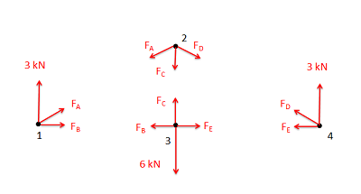
The method of joints focuses on the joints, or the connection points where the members come together. We assume we have a pin at each of these points that we model as a particle, we draw out the free body diagram for each pin, and then write out the equilibrium equations for each pin. This will result in a large number of equilibrium equations that we can use to solve for a large number of unknown forces.
The method of sections involves pretending to split the truss into two or more different sections and then analyzing each section as a separate rigid body in equilibrium. In this method, we determine the appropriate sections, draw free-body diagrams for each section, and then write out the equilibrium equations for each section.
The method of joints is usually the easiest and fastest method for solving for all the unknown forces in a truss. The method of sections, on the other hand, is better suited to targeting and solving for the forces in just a few members without having to solve for all the unknowns. In addition, these methods can be combined if needed to best suit the goals of the problem solver.
Source: Engineering Mechanics, Jacob Moore, et al. https://mechanicsmap.psu.edu/websites/5_structures/5-1_structures/structures.html
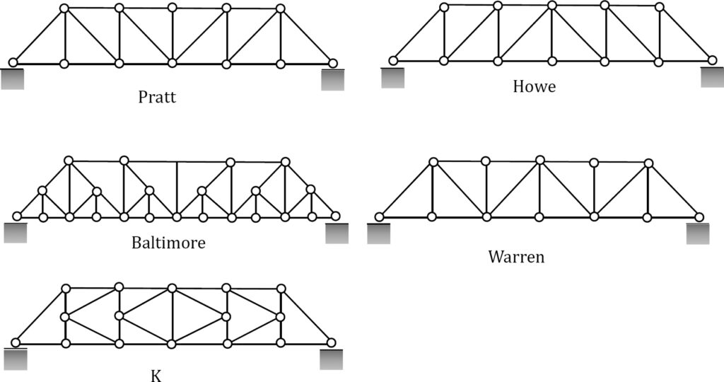
Here are common types of bridge trusses:
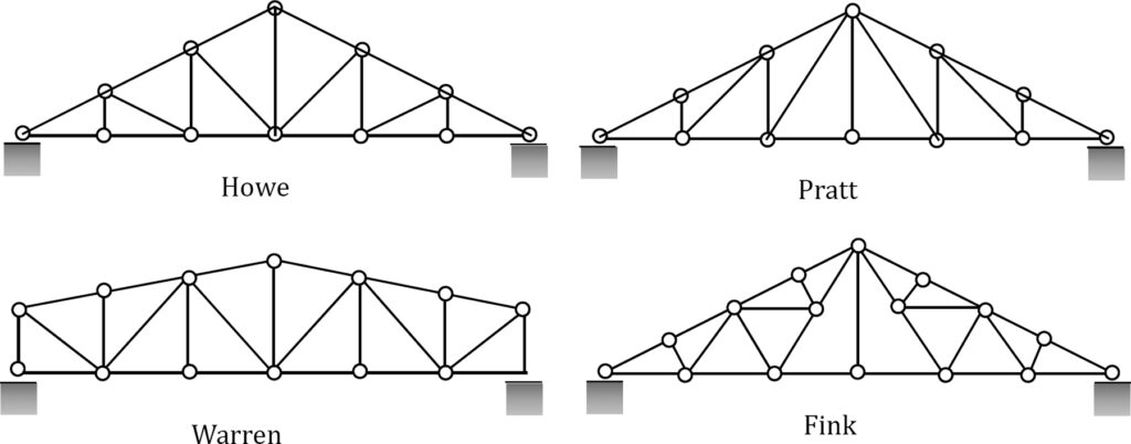
Here are common types of roof trusses:
5.1.3 Parts of a Truss
A truss is composed of:
- joints
- members, and
- external forces (reaction forces and applied forces).
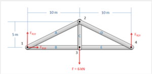
The joints are often labelled with a letter and are where the external forces and members connect.
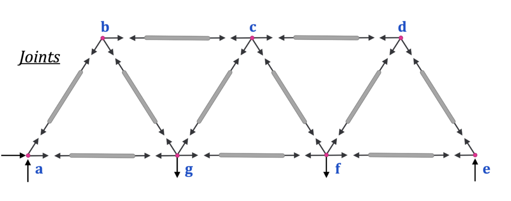 Here is an example of just the joints without the members:
 Source: Engineering Mechanics, Jacob Moore, et al. https://mechanicsmap.psu.edu/websites/5_structures/5-3_method_of_joints/methodofjoints.html
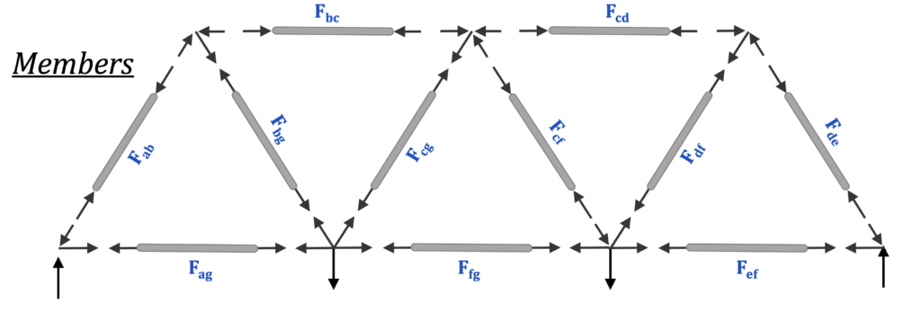
The members are the metal or wooden beams that are labelled with the connection between joints. For example member AB connects joints A and B.
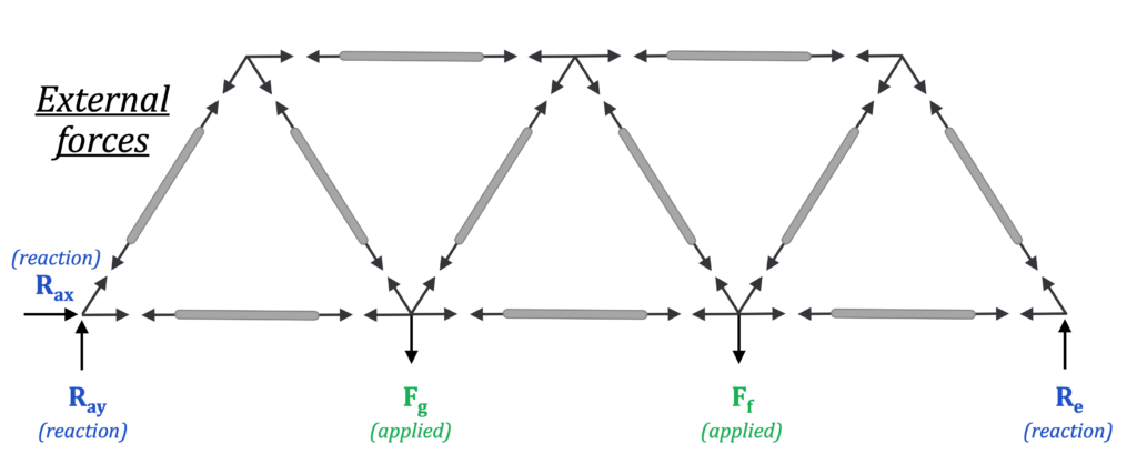
The external forces are the reaction forces and the applied forces. The applied forces come from the load distributed across the bridge or from the roof.
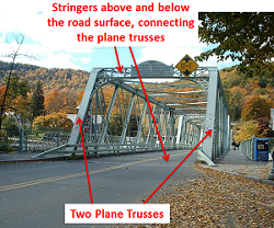
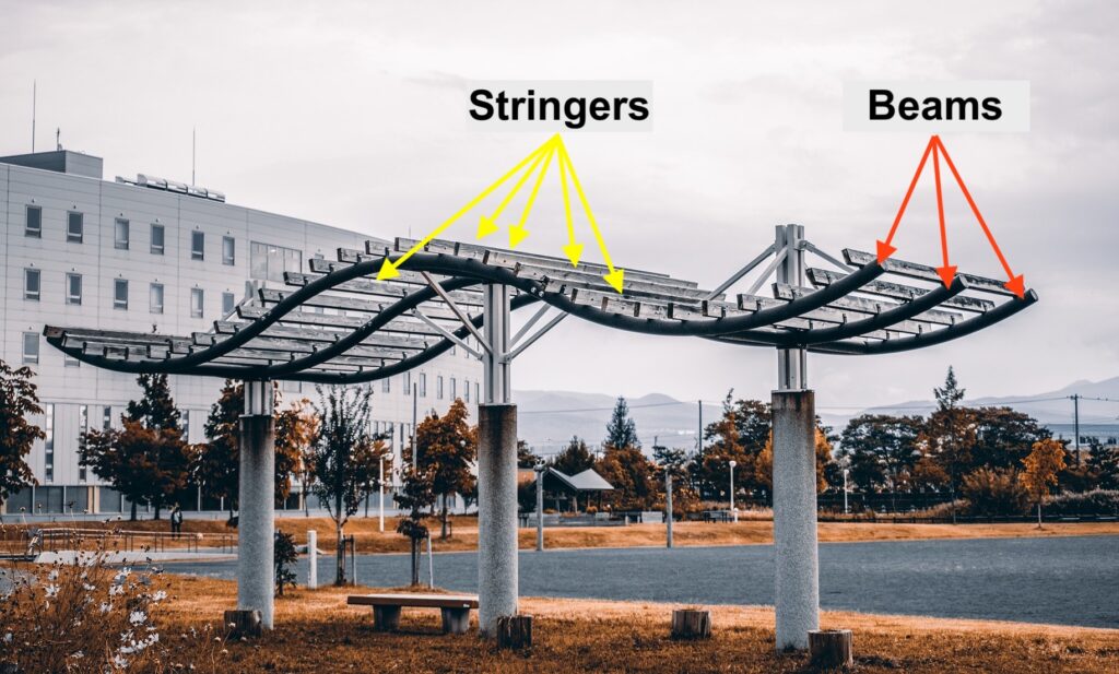
The applied force/load from trucks and cars goes from the deck to the stringers, across the beams, to the joints of the truss, where it is carried as applied (external) forces on the edges of the bridge.

Here is a second type of structure. Which are the stringers and which are the beams?

.
.
.
.
.
.
Any ideas?
.
.
.
.
.
Here’s the answer!
Here are some examples of how to convert the reaction forces/moments for a truss. Note: these are the same as in section 3.4.
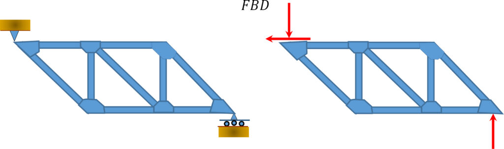

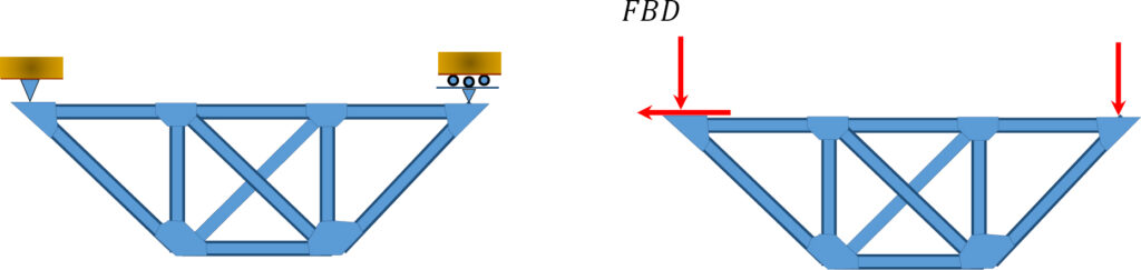
Source: Internal Forces in Beams and Frames, Libretexts. https://eng.libretexts.org/Bookshelves/Civil_Engineering/Book%3A_Structural_Analysis_(Udoeyo)/01%3A_Chapters/1.05%3A_Internal_Forces_in_Plane_Trusses
5.1.4 Tension & Compression
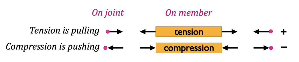
The two-force members carry internal forces in either tension or compression between the joints. One standard sign convention is to assume all members are in tension, labelled as positive (+), then any negative number (-) means the member is in compression.
Following Newton’s 3rd law regarding equal and opposite reactions, when there is tension in a member, there is also tension in a joint. Pulling on the member (tension) in turn pulls on the joint. Similarly, pushing on a member (compression) pushes on the joint as well.
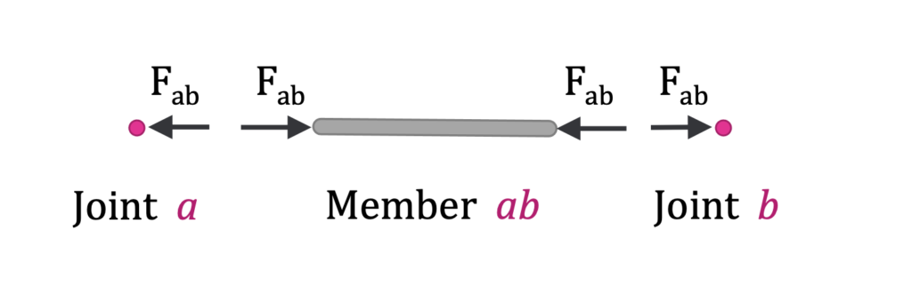
Similarly, the force from member AB (Fab) is distributed from joint a through member ab to joint b. Shown here in compression, Fab is negative. The magnitude of Fab on joint a is the same as the magnitude on joint b, even though they are pointing in two different directions (hence equal and opposite). Member bc will have a different magnitude.
When you look at each joint, compression (-) appears to be pushing on the joint while tension (+) is pulling on it with the force named for the member ( Fab ).
In the next section, we will discuss each of these methods in greater detail and how to solve problems using them.
Key Takeaways
Basically: A truss is a rigid structure composed of two force members (where forces are applied at only two locations) that connect at joints and have external forces applied. The internal forces of the truss put members in compression (-) or tension (+).
Application: The frame of a roof is often composed of a wooden truss, and trusses are commonly found in wooden and metal bridges.
Looking Ahead: The next two sections discuss the method for calculating the force in the members & you’ll talk about trusses more in your Structures course.
A two force member is a body that has forces (and only forces, no moments) acting on it in only two locations.
