
Chapter 4: Rigid Bodies
4.2 Rigid Body Free Body Diagrams
Following what we learned in Section 2.2 on particle Free-Body Diagrams (FBDs), this section will expand on that for rigid bodies. The biggest difference between a particle and a rigid body FBD is where the force is applied. In a rigid body FBD, you have to be precise about pointing the head of the force arrow to the location where it is applied. For example, if we wanted to make an FBD of you and me high-fiving, you would apply the force from your hand onto my hand, not at my center of mass.
In this section, first we will learn how to do a FBD for a part, then we will look at how to model a system of multiple objects.
4.2.1 Part FBD
When modelling a single object using an FBD, you are simplifying a complex problem into specific forces using arrows and an object floating in space. The floor becomes a normal force arrow and a frictional force arrow. Pushing or pulling on an object becomes an applied force with the arrow pointing to or from (pushing or pulling) the location where the pushing or pulling occurs. Remember the rules from section 2.2 still apply:
- Add coordinate frame (which way is positive x and positive y?)
- Replace surfaces with forces (floor, hand, and objects touching it become arrows)
- Point forces in the correct direction (the head of the arrow points to where the force acts. FG acts down)
- Use unique (different) names (be sure to name each force with a different name).
Here are some tips to keep in mind about each of the forces:
- Gravity acts on every particle in an object. Because we don’t want a million little arrows on the object, we sum the effect of gravity at the center of mass. This is also because we generally know the total mass of something and where that occurs on an object (often at the geometric center), so we concentrate the force of gravity at this center of mass.
- Normal forces always act perpendicular to the surface, so if the ground is at an angle, then the normal force acts 90 degrees from that angle (perpendicular).
- Frictional forces act parallel to the plane between the two surfaces. This makes it a shear force, which we’ll look at in Chapter 6.
- Friction always opposes motion, a fact that will be very important in your dynamics class.
- Spring force is often shown as negative because the force acts in the opposite direction of the motion travelled. In application, you set the direction of the frictional force to match if it is pushing or pulling.
- Applied forces (and moments), such as distributed loads, motors, pushing on an object, tension, etc.
The steps to make an FBD are:
- Draw shape
- Add a coordinate frame
- Replace forces with arrows
- Label each force uniquely
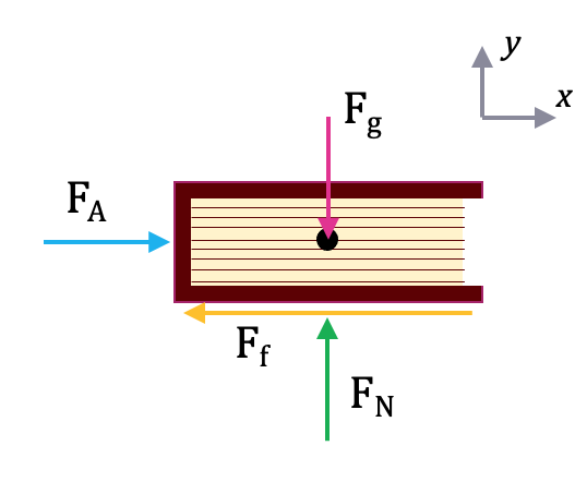
To model a book being pushed across the table, you would apply the following forces at the following locations (see image below)
- The normal force on the bottom of the book (green arrow)
- The frictional force running along the bottom surface between the book and the table (yellow arrow)
- The gravitational force acting at the center of mass (pink arrow)
- any applied force at the point of application, such as your hand pushing on the book (blue arrow)
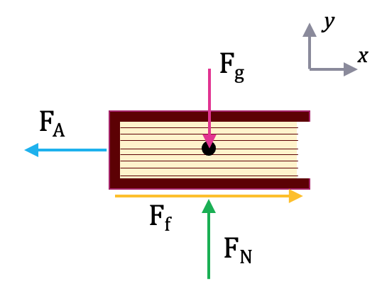
If instead, the book were being pulled by a string, the image would be the same, but the applied force and frictional force would change direction (because friction always opposes motion).
A free body diagram is a tool used to solve engineering mechanics problems. As the name suggests, the purpose of the diagram is to “free” the body from all other objects and surfaces around it so that it can be studied in isolation. We will also draw in any forces or moments acting on the body, including those forces and moments exerted by the surrounding bodies and surfaces that we removed.
The diagram below shows a ladder supporting a person and the free body diagram of that ladder. As you can see, the ladder is separated from all other objects and all forces acting on the ladder are drawn in with key dimensions and angles shown.
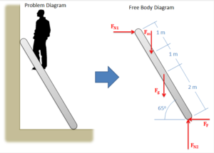
The first step in solving most mechanics problems will be to construct a free-body diagram. This simplified diagram will allow us to more easily write out the equilibrium equations for statics or strengths of materials problems, or the equations of motion for dynamics problems.
To construct the diagram, we will use the following process.
- First, draw the body being analyzed, separated from all other surrounding bodies and surfaces. Pay close attention to the boundary, identifying what is part of the body and what is part of the surroundings.
- Second, draw in all external forces and moments acting directly on the body. Do not include any forces or moments that do not directly act on the body being analyzed. Do not include any forces that are internal to the body being analyzed. Some common types of forces seen in mechanics problems are:
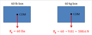
- Gravitational Forces: Unless otherwise noted, the mass of an object will result in a gravitational weight force applied to that body. This weight is usually given in pounds in the English system, and is modelled as 9.81 (g) times the mass of the body in kilograms for the metric system (resulting in a weight in Newtons). This force will always point down towards the center of the Earth and act on the center of mass of the body.
Gravitational forces always act downward on the center of mass. - Normal Forces (or Reaction Forces): Every object in direct contact with the body will exert a normal force on that body, which prevents the two objects from occupying the same space at the same time. Note that only objects in direct contact can exert normal forces on the body.
- An object in contact with another object or surface will experience a normal force that is perpendicular (hence normal) to the surfaces in contact.
Normal forces always act perpendicular to the surfaces in contact. The barrel in the hand truck shown on the left has a normal force at each contact point. - Joints or connections between bodies can also cause reaction forces or moments, and we will have one force or moment for each type of motion or rotation the connection prevents.
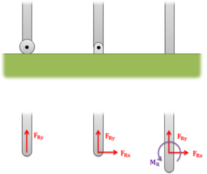
The roller on the left allows for rotation and movement along the surface, but a normal force in the y direction prevents motion vertically. The pin joint in the center allows for rotation, but normal forces in the x and y directions prevent motion in all directions. The fixed connection on the right has a normal force preventing motion in all directions and a reaction moment preventing rotation.
- An object in contact with another object or surface will experience a normal force that is perpendicular (hence normal) to the surfaces in contact.
- Friction Forces: Objects in direct contact with the body can also exert friction forces on the body, which will resist the two bodies sliding against one another. These forces will always be perpendicular to the surfaces in contact. Friction is the subject of an entire chapter in this book, but for simple scenarios, we usually assume rough or smooth surfaces.
- For smooth surfaces, we assume that there is no friction force.
- For rough surfaces, we assume that the bodies will not slide relative to one another, no matter what. In this case, the friction force is always just large enough to prevent this sliding.
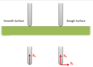
For a smooth surface, we assume only a normal force perpendicular to the surface. For a rough surface, we assume normal and friction forces are present.
- Tension in Cables: Cables, wires or ropes attached to the body will exert a tension force on the body in the direction of the cable. These forces will always pull on the body, as ropes, cables and other flexible tethers cannot be used for pushing.
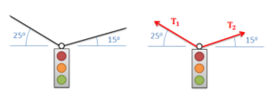
The tension force in cables always acts along the direction of the cable and will always be a pulling force. - The above forces are the most common, but other forces such as pressure from fluids, spring forces and magnetic forces may exist and may act on the body.
- Normal Forces (or Reaction Forces): Every object in direct contact with the body will exert a normal force on that body, which prevents the two objects from occupying the same space at the same time. Note that only objects in direct contact can exert normal forces on the body.
- Gravitational Forces: Unless otherwise noted, the mass of an object will result in a gravitational weight force applied to that body. This weight is usually given in pounds in the English system, and is modelled as 9.81 (g) times the mass of the body in kilograms for the metric system (resulting in a weight in Newtons). This force will always point down towards the center of the Earth and act on the center of mass of the body.
- Once the forces are identified and added to the free body diagram, the last step is to label any key dimensions and angles on the diagram.
Source: Engineering Mechanics, Jacob Moore, et al. http://wwhttp://mechanicsmap.psu.edu/websites/1_mechanics_basics/1-6_free_body_diagrams/free_body_diagrams.htmlw.oercommons.org/courses/mechanics-map-open-mechanics-textbook/view
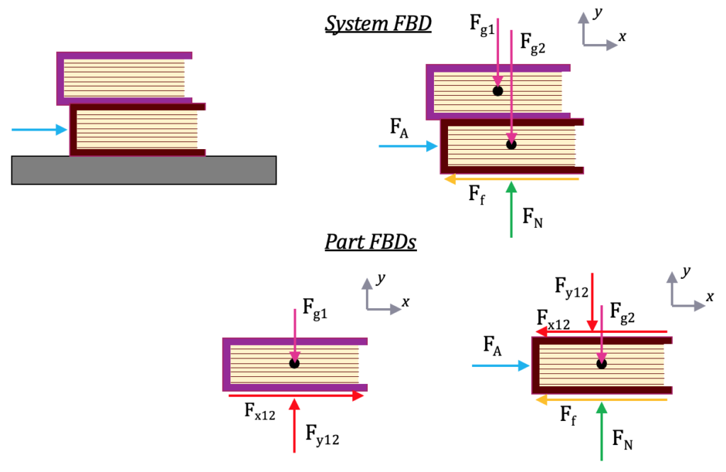
4.2.2 System FBD
A system free-body diagram is composed of multiple parts, so you can have multiple ‘levels’ to consider: the system level with all objects on the same FBD, and a part FBD for each individual part. This is especially helpful if you have more unknowns than equations when using the equilibrium equations, so you can find more information by splitting the system up into individual parts.
For the system FBD, you look at the parts combined together and add only the external forces (gravity, applied, normal, frictional, spring). When you look at each part separately, you now have to include the interaction between the objects, replacing a part with forces (generally 2 forces: vertical and horizontal forces).
For example, if there are 2 books stacked on top of each other, you now need 3 FBDs:
- a system-level FBD with both books,
- a part FBD for the bottom book, with the top book replaced by arrows (forces)
- a part FBD for the top boo,k with the bottom book replaced by arrows (forces)
To make a system FBD:
- Draw system FBD using unique consistent labels (ie, a letter or number per part)
- The system should be floating in space with no surface (such as the floor)
- Include a coordinate frame
- Use only external forces on the system FBD (gravity, applied, normal, frictional, spring).
- DO NOT include internal forces
- It is especially important to use unique labels, so the top book forces are labelled 1, and the bottom book forces are labelled 2 (or T for top and B for bottom, or A and B).
- Draw a FBD for each part separately & coordinate frame with equal and opposite arrows for internal system forces
-
- The part should be floating in space with no surfaces or other objects
- Include a coordinate frame (yes, again! This is to ensure you didn’t rotate the object).
- Copy the external forces onto the part FBD from the system FBD with the identical labels and arrow directions
- Now add internal forces, replacing the other object with force arrows (red arrows)
- When you draw the second part FBD, follow the above bullets for the second object (with label 2 instead of 1, copying the system-level external force labels). Note, though, that you use the same labels for the internal forces from the first part FBD, but the direction is reversed (left becomes right and up becomes down). Following Newton’s laws, the objects exert equal and opposite forces on each other, and should cancel out at the system level, so they have the same label (magnitude) and opposite directions.
Some tips:
- Differentiate one object from the other through the labels, using either a letter or a number for each part. These same labels go on the system-level FBD (except for the internal labels).
- Use the same labels between the part and system FBDs for external forces. Don’t change the label – that will make the equations impossible to solve and look like you have more unknowns.
- Use the same unique labels between the internal forces for the part FBDs, but in the opposite direction.
- If you know the location of the center of mass, you could combine the gravitational forces into 1 system level gravitational force. You could also model the gravitational force as one force per part acting at the center of mass for each object. This is a better method if you have to separate the objects to do the calculations.
4.2.3 Examples
Here are some examples from: http://mechanicsmap.psu.edu/websites/1_mechanics_basics/1-6_free_body_diagrams/free_body_diagrams.html
Example 1: Part FBD
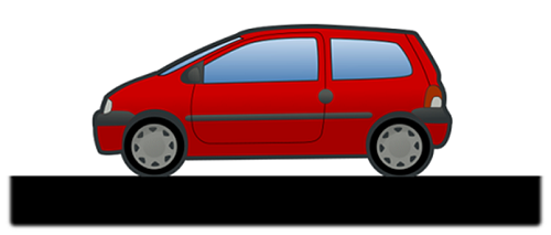
The car shown below is moving and then slams on the brakes, locking up all four wheels. The distance between the two wheels is 8 feet, and the center of mass is 3 feet behind and 2.5 feet above the point of contact between the front wheel and the ground. Draw a free-body diagram of the car as it comes to a stop.
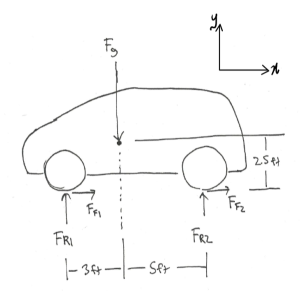
Source: Engineering Mechanics, Jacob Moore et al., http://mechanicsmap.psu.edu/websites/1_mechanics_basics/1-6_free_body_diagrams/pdf/P3.pdf
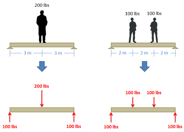
Example 2: Part FBD (a beam)
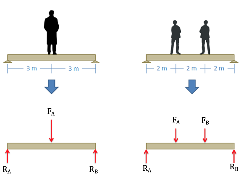
Image adapted. Source: Engineering Mechanics, Jacob Moore, et al. http://mechanicsmap.psu.edu/websites/4_statically_equivalent_systems/4-1_statically_equivalent_systems/images/equivalentexample.png
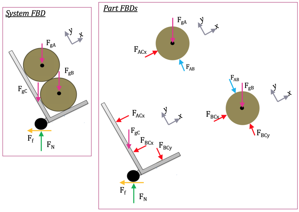
Example 3: System FBD
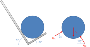
Two equally sized barrels are being transported in a hand truck as shown below. Draw a free-body diagram of each of the two barrels.
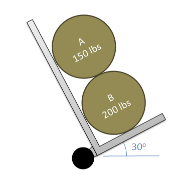
Source: Engineering Mechanics, Jacob Moore et al., http://mechanicsmap.psu.edu/websites/1_mechanics_basics/1-6_free_body_diagrams/pdf/P2.pdf
External forces are in green, pink, and yellow. Internal forces between the cart and barrels (C and A/B) in red and between the barrels (A & B) in blue. Notice the matching labels for internal forces but opposing directions. Notice that the coordinate frame has been rotated consistently in all of the FBDs.
Key Takeaways
Basically, A part free-body diagrams (FBDs) give you a way to model complicated problems in a simple way with arrows. Systems FBDs allow you to combine objects and analyze them separately.
Application: A bat swinging could be modelled as a part FBD with gravity and multiple applied forces (hands on one end and the ball on the other). You could model the moment the bat and ball are touching using a system FBD.
Looking ahead: You’ll use an FBD in every step 2 in nearly every homework problem. These are especially helpful with Equilibrium Equations in the next section.
