
Chapter 6: Internal Forces
6.3 Examples
Here are examples from Chapter 6 to help you understand these concepts better. These were taken from the real world and supplied by FSDE students in Summer 2021. If you’d like to submit your own examples, please send them to the author eosgood@upei.ca.
Example 6.3.1: Internal Forces, Submitted by Emma Christensen
1. Problem
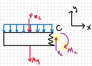
The setup that holds the solar panels at the UPEI FSDE is modelled below. Considering beam S (1.9 m length), find the internal forces at point C. Assume the intensity of the solar panel on the beam is 220 N/m.
Sketch:
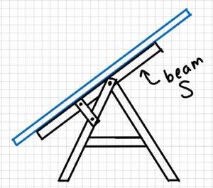
Model:
2. Draw
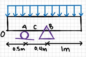
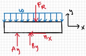
Free-body diagram:
3. Knowns and Unknowns
Knowns:
- w = 220 N/m
- OA = 0.5 m
- AC = 0.2 m
- AB = 0.4 m
- L = 1.9 m
Unknowns:
- Nc
- Vc
- Mc
4. Approach
Use equilibrium equations. First, solve for reaction forces, then make a cut at C and solve for the internal forces.
5. Analysis
[latex]w=\frac{F}{L}\\F=wL\\F_R=220N/m\cdot 1.9m\\F_R=418N\\\sum F_X=0=B_X[/latex]
Find reaction forces:
[latex]\sum M_A=0=B_y(0.4m)-F_R(0.45m)\\(0.4m)B_y=418N(0.45m)\\B_y=\frac{188.1 N\cdot m}{0.4m}\\B_y=470.25N[/latex]
[latex]\sum F_y=0=-F_R+A_y+B_y\\A_y=F_R-B_y\\A_y=418N-470.25N\\A_y=-52.25N[/latex]
The answer we got for Ay is negative, which means that the arrow should be drawn in the other direction. We will change it for our next sketch.
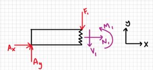
Make a cut at C:
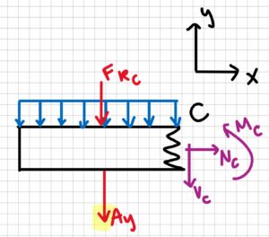
Now solve for the internal forces:
[latex]\sum F_x=0\:\:;\:\:N_c=0\\\sum F_y=0=-A_y-V_c-(w\cdot L_A)\\V_c=-52.25N-(220N/m\cdot 0.7m)\\V_c=-206.25 N\\\sum M_c=A_y(0.2m)+M_c+(F_{Rc}\cdot 0.35m)\\M_c=52.25 N (0.2m)+(220N/m\cdot 0.7m\cdot 0.35m)\\M_c=64.35N\cdot m[/latex]
Final FBD, showing the arrows in the correct directions:
6. Review
It makes sense that Ay and By are in different directions because the resultant force Fr of the solar panel on the beam is not between A and B. It also makes sense that the moment at C is in the counterclockwise direction rather than the clockwise direction when you think about the direction of the forces applied to the beam.
Example 6.3.2: Shear/Moment Diagrams, Submitted by Deanna Malone
1. Problem
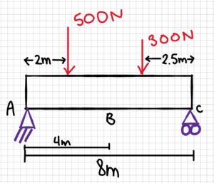
A beam that is simply supported has two point loads acting on it. One acts 2 m from point A, and the other acts at 2.5 m from C. Point B is in the middle of the beam. The first point load is 500 N and the second is 300 N. What are the internal forces at point B? Solve for reaction forces and include a shear/moment diagram.
2. Draw
Sketch:
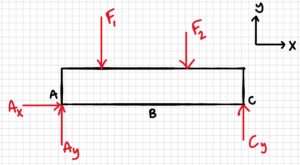
Free-body diagram:
3. Knowns and Unknowns
Knowns:
- F1 = 500 N
- F2 = 300 N
Unknowns:
- Ay
- Ax
- Cy
- VB
- MB
- NB
4. Approach
Shear/moment equations, EOM equations
5. Analysis
Solve for reaction forces:
(Ax, Cy)
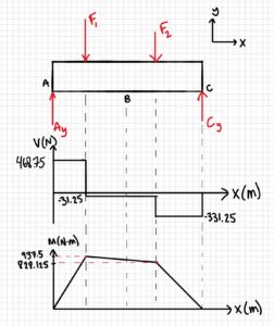
[latex]\begin{aligned} \sum F_{x}=0=A_{x}=0 \\ \sum M_{A}=0 &=-F_{1} \cdot 2 m-F_{2} \cdot 5.5 m+C_{y} \cdot 8 m \\ C_{y}=&\frac{F_{1} \cdot 2 m+F_{2} \cdot 5.5 m}{8m} \\ C_{y} &=\frac{500 N \cdot 2 m+300 N \cdot 5.5 m}{8 m} \\ C_{y} &=331.25 \mathrm{~N} \end{aligned}[/latex]
(Ay)
[latex]\begin{aligned} \sum F_{y}=0 &=A_{y}+C_{y}-F_{1}-F_{2} \\ A_{y} &=F_{1}+F_{2}-C_{y} \\ A_{y} &=500 \mathrm{~N}+300 \mathrm{~N} - 331.25 \mathrm{~N} \\ A_{y} &=468.75 \mathrm{~N} \end{aligned}[/latex]
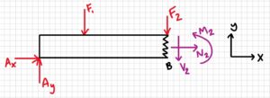
Cut 1: at B
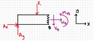
[latex]\begin{aligned} \sum F_{X}=0=A_{X} &+N_{B}=0 \\ & N_{B}=0 \\ \sum F_{y}=0 &=A_{y}-V_{B}-F_{1} \\ V_{B} &=A_{y}-F_{1} \\ V_{B} &=468.75 N - 500 N \\ V_{B}=-31.25 N \end{aligned}[/latex]
[latex]\begin{aligned} \sum M_{B}=& 0=-A_{y}(4 m)+F_{1}(2 m)+M_{B} \\ & M_{B}=A_{y}(4 m)-F_{1}(2 m) \\ & M_{B}=468.75 N(4 m)-500 N(2 m) \\ M_{B} &=875 \mathrm{~N} \cdot \mathrm{m} \end{aligned}[/latex]
Cut 2: At the point where F1 is applied
[latex]\begin{aligned} \sum M_{1}=0 &=-A_{y}(2 m)+M_{1}=0 \\ M_{1} &=A_{y}(2 m) \\ M_{1} &=468.75 N(2 m) \\ M_{1} &=937.5 \mathrm{~N} \cdot m \end{aligned}[/latex]
Cut 3: At the point where F2 is applied
[latex]\begin{aligned} \sum M_{2}=0 =-A_{y}(5.5 \mathrm{~m})+F_{1}(3.5 \mathrm{~m})+M_{2} \\ M_{2} =A_{y}(5.5 \mathrm{~m})-F_{1}(3.5 \mathrm{~m}) \\ M_{2} =468.75 \mathrm{~N}(5.5 \mathrm{~m})-500 \mathrm{~N}(3.5 \mathrm{~m}) \\ M_{2} =828.125 \mathrm{~N} \cdot \mathrm{m} \end{aligned}[/latex]
Answer: NB = 0, VB = -31.25 N, MB = 875 Nm
6. Review
The reaction forces make sense as they offset the applied forces. The shear/moment diagrams returned to zero, so they are correct too. The moment found at B is in the moment diagram; it is smaller than the maximum.
Example 6.3.3: V/M Diagrams, Submitted by Luciana Davila
- Problem
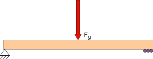
For the 8cm simply supported beam given below, if Fg, which is applied at the center of the beam, is given as 30 N, find the internal forces between the reaction forces and draw the V-M diagram for the beam.
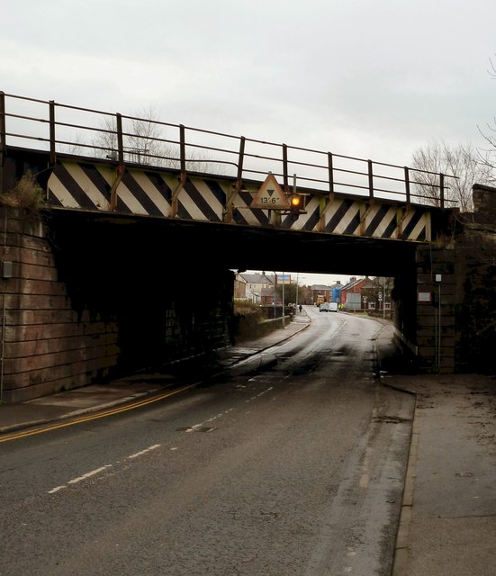
Simply supported girder bridge: https://www.geograph.org.uk/photo/2780207
2. Draw
3. Knowns and Unknowns
Knowns:
- Fg = 30N
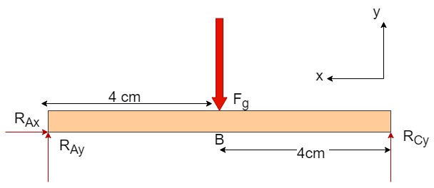
- r AB = r BC = 0.04 m
Unknowns:
- Reaction forces = RAx, RAy, RCy
- For the segment of beam AB nd BC,
- Shear = V, V2
- Bending Moment = M, M2
- Normal force = N, N2
4. Approach
Find reaction forces from equilibrium equations. Use them to find the shear and bending moment of segment AB and BC. Draw the V-M diagram from the answers.
5. Analysis
Finding reaction forces:
[latex]\sum F_x=0=R_{Ax}\\R_{Ax}=0N[/latex]
Solving for RCy:
[latex]\sum M_A=0= -(r_{AB}\cdot F_g)+(r_{AC}\cdot R_{Cy})\\r_{AB}\cdot F_{g}=r_{AC}\cdot R_{Cy}[/latex]
[latex]R_{Cy}=\frac{r_{AB}\cdot F_g}{r_{AC}}\\R_{By}=\frac{0.04m\cdot 30 N}{0.08 m}[/latex]
[latex]R_{Cy}=15 N[/latex]
Solving for RAy:
[latex]\sum F_y=0=R_{Cy}+R_{Ay} -F_g\\R_{Ay}=F_g-R_{Cy}\\R_{Ay}= 15 N[/latex]
Finding shear and Moment from A to B :
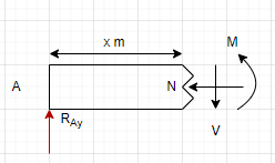
[latex]\sum F_x=0\\N=0N[/latex]
Solving for V
[latex]\sum F_y=0=R_{Ay}+-V\\ V= 15 N[/latex]
Solving for M :
[latex]\sum M_A=0= -( V\cdot 0.04) +M\\M = 15\cdot 0.04\\M=0.6N[/latex]
Finding shear and Moment from B to C:
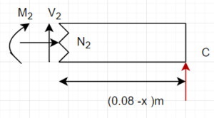
[latex]\sum F_x=0\\N=0N[/latex]
Solving for V
[latex]\sum F_y=0=R_{Cy}+V_2\\ V_2= -15 N[/latex]
Solving for M :
[latex]\sum M_C=0= -( V_2\cdot(0.04) -M_2\\M_2 = 15\cdot 0.04\\M=0.6N[/latex]
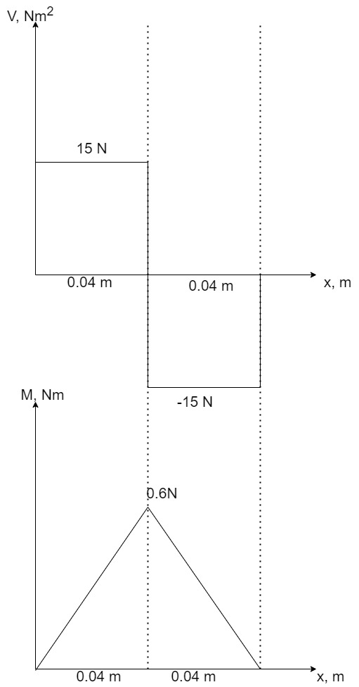
V-M diagram:
For the V-x graph, from A to B, there is a constant shear of 15 N, then from B to C, the shear has the same magnitude but a different direction. To plot the M-x graph, substitute x in the equation for M and M2 to find the peak bending moment. Also, because M is the integral of shear force, horizontal plots in shear correspond to a linear plot in the M-x graph.
6. Review
The answers make sense. The moment, shear, and reaction forces are equal in both segments of the beam. This is as expected because of the symmetry of the beam.
Example 6.3.4: V/M Diagrams, Submitted by Michael Oppong-Ampomah
1. Problem
2. Sketch
N/A, Sketch Provided.
3. Knows and Unknowns:
Knowns:
- Distributed Load: w
- Dimensions and shown
Unknown:
- Shear/Moment Diagram
4. Approach:
Break the beam into sections as forces change.
Determine the plotted shape of the shear and moment of each section.
Draw the V/M diagrams using these shape diagrams.
5. Analysis:
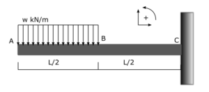
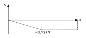
A distributed load creates a linear section across it, with the magnitude of the shear force increasing across the load. The maximum shear will be at the end of the distributed load. With no other forces being applied except for reactions, section B-C should be constant. Since the beam is static, the reactions must bring the shear back to zero.
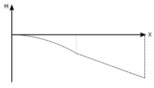
The moment can be drawn using the knowledge that dM = V. Section A-B in the shear diagram is linear; integrating a linear function gives a quadratic function, thus, section A-B in the moment diagram must be curved. Section B-C is constant in shear. Integrating a constant function gives a linear function; therefore, the moment across this section must be linear, and since the shear is negative, the slope of the moment must be negative. Finally, because the beam is static, the moment must return to zero due to the reaction forces.
6. Review
Using principles of shear force (V) and moments and their integral/derivative relationship, the shear and moment diagrams make sense for their general shape.
Example 6.3.5: V/M Diagrams, Submitted by William Craine
1. Problem
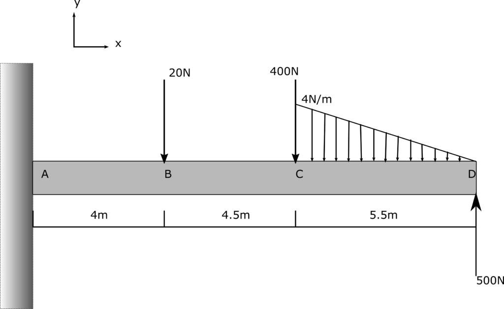
2. Draw
[latex]4N/m \cdot \frac{5.5m}{2} = 11N[/latex]
[latex]\bar{x} = 1/3 \cdot 5.5m = 1.83m[/latex]
[latex]\bar{x} \ from A = 4m + 4.5m + 1.83m = 10.3m[/latex]
3. Knowns and Unknowns
Knowns:
- Applied Forces:
- FB = -20N
- FC = -400N
- FD = 500N
- FLoad = -4N/m
- Dimensions as shown
Unknowns:
- Reaction Forces: RAX, RAY, MA
- Shear/Moment Diagram
4. Approach
- Use the equilibrium equation to find the reaction forces
- Use beam analysis/cutting between forces to find equations for the shear/moment diagram.
5. Analysis
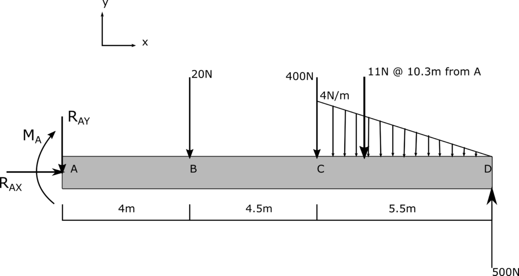
First, use the sum of forces and the sum of moments to determine RAy and MA.
[latex]\sum F_x = R_{Ax} = 0[/latex]
[latex]\sum F_y = -R_{Ay} - 20N - 400N - 11N +500N = 0[/latex]
[latex]R_{Ay} = 69N[/latex]
[latex]\sum M_A = - M_A - (20N \cdot 4m) - (400N \cdot 8.5m) - (11N \cdot 10.3m) + (500 N \cdot 14m) = 0[/latex]
[latex]M_A = 3406.7Nm[/latex]
Next, cut the beam between A and B and analyze the internal forces.
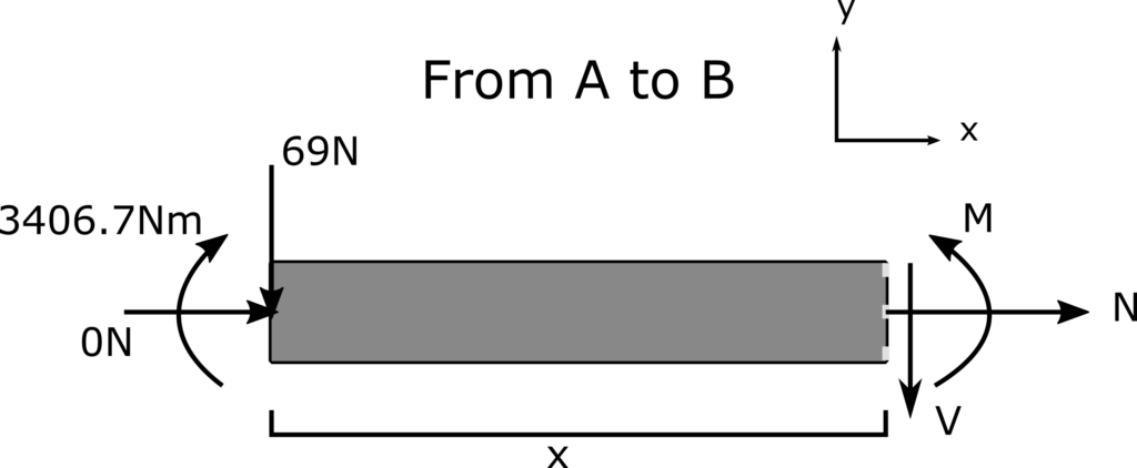
[latex]\sum F_x = N + 0 = 0 \\ N = 0[/latex]
[latex]\sum F_y = -69N -V = 0 \\ V= -69N[/latex]
[latex]\sum M_{cut} = M + (69N \cdot x) - (3406.7Nm) = 0 \\ M = -69x + 3406.7[/latex]
Repeat the analysis of internal forces from A to C.
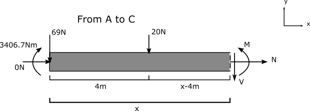
[latex]\sum F_x = N + 0 = 0 \\ N = 0[/latex]
[latex]\sum F_y = -69N - 20N -V = 0 \\ V = -89N[/latex]
[latex]\sum M_{cut} = M + (69N \cdot x) + (20N \cdot{(x-4m)}) - 3406.7Nm = 0 \\ M+89x-3326.7Nm = 0 \\ M = -89x + 3326.7[/latex]
Finally, analyze the beam in the area from C to D. Ensure that the value of X used is now taken from point D.
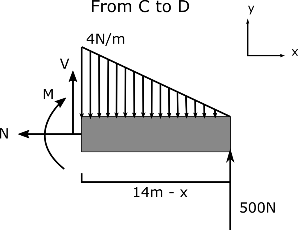
[latex]\sum F_x = -N = 0 \\ N = 0[/latex]
Since the section does not reach the end of the distributed load, the slope of the load must be calculated:
[latex]\frac{4}{5.5} = \frac{m}{14-x} \\ m = \frac{56-4x}{5.5}[/latex]
This can be used to find the equivalent point load in terms of x.
[latex]F_{eq} = \frac{\frac{56-4x}{5.5} \cdot (14-x)}{2} \\ F_{eq} = \frac{4x^2}{11} - \frac{112x}{11} + \frac{784}{11}[/latex]
This point load can be used when summing forces to find v.
[latex]\sum F_y = 0 = V - F_{eq} + 500 \\ V = F_{eq} - 500 \\ V = \frac{4x^2}{11} - \frac{112x}{11} + \frac{784}{11} - 500 \\ V = \frac{4x^2}{11} - \frac{112x}{11} - 428.7[/latex]
To save time, rather than use the sum of moments to determine the equation for moments in this section, the moment can be found by the integral of V.
[latex]M = \int \frac{4x^2}{11} - \frac{112x}{11} - 428.7 dx \\ M = \frac{4x^3}{33} - \frac{112x^2}{22} - 428.7x +C[/latex]
We know that for this beam to be static, the moment at x=14m must be 0. This can be used to determine C.
[latex]M(14) = 0 = \frac{4(14)^3}{33} - \frac{112(14)^2}{22} - 428.7(14) +C \\ C = 6667 \\ Therefore: M_{cd}(x) = \frac{4x^3}{33} - \frac{112x^2}{22} - 428.7x + 6667[/latex]
With the values for internal forces found between each change in force, the internal forces can be plotted.
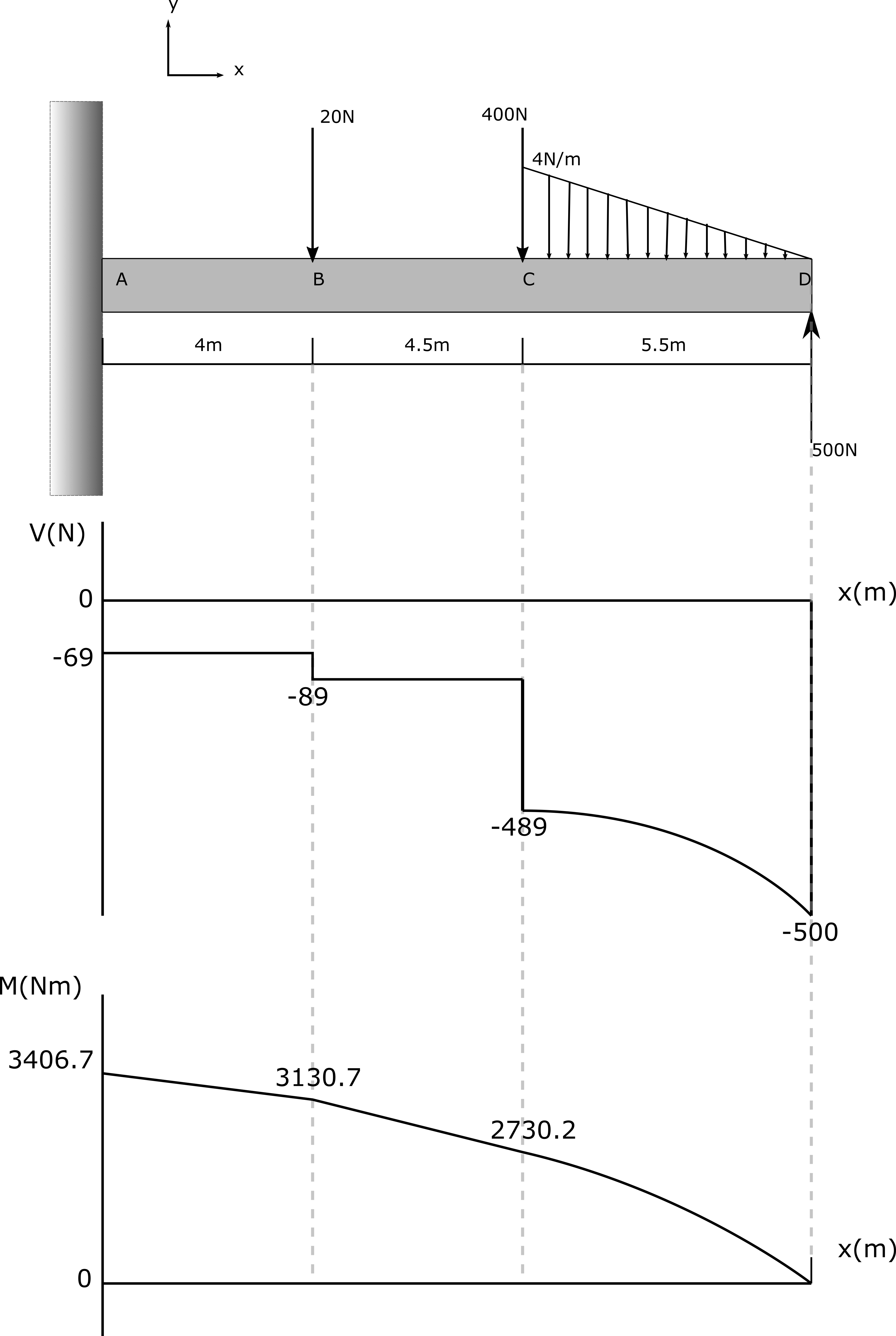
6. Review
Using principles of shear force (V) and moments and their integral/derivative relationship, the shear and moment diagrams make sense for their general shape. The numerical values calculated align with the variables provided.
Example 6.3.6: Internal Forces, Submitted by Riley Fitzpatrick
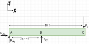
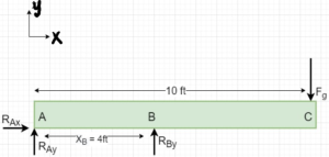
1. Problem
2. Draw
3. Knowns and Unknowns
Knowns:
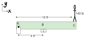
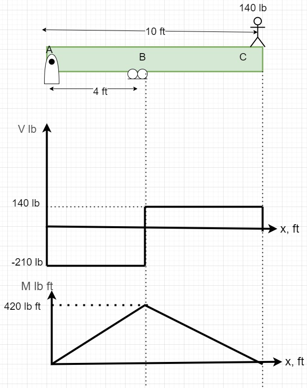
- Fg = 140 lbs
- XA= 0 ft
- XB= 4 ft
- XC= 10 ft
Unknowns:
- RAx
- RBx
- RAy
- Internal forces N, V, M between B and C, & A and B
4. Approach
Calculate the reaction forces using equilibrium equations. Cut the diving board between A & B, and use equilibrium equations to find internal forces. Do the same to find internal forces between B and C. Use the values to draw the shear and moment diagram.
5. Analysis
a.
[latex]\sum{F_{x}} = 0=R_{Ax}[/latex]
[latex]\sum{F_{y}}=0=R_{Ay}+R_{By}-140 lb \\R_{Ay}+R_{By}=140 lb[/latex]
[latex]\sum{M_{A}}=\left(X_{B} \cdot R_{By}\right)-\left(X_{c} \cdot F_{g}\right)=0[/latex]
[latex]R_{By}= \frac{X_{c}\cdot F_{g}}{X_{B}}\\R_{By}= \frac{10 ft\cdot 140 lb}{4 ft}[/latex]
[latex]R_{By}=350 lb[/latex]
now, [latex]R_{Ay}=140 lb - R_{By}\\ \kern 1pc=140 lb - 350 lb \\ \kern 1pc =-210 lb[/latex]
The negative sign for [latex]R_{Ay}[/latex] means that the direction of [latex]R_{Ay}[/latex] is not +y but in the -y direction.
Thus, the reation forces are [latex]R_{Ay}=-210 lb, R_{By} = 350 lb, R_{Ax}=0[/latex]
b. Finding internal forces between A and B
To find the internal forces between A and B, cut in the middle of A and B, giving [latex]x = \frac{X_{B}}{2} =2 ft[/latex]
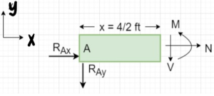
[latex]\sum{F_{x}} = 0=R_{Ax} + N\\ N = 0[/latex]
[latex]\sum{F_{y}}=0=-V - R_{Ay}\\ V = -R_{Ay}\\V=-210 lb[/latex]
[latex]\sum{M_{A}}=0\\ \kern 2pc =M-xV\\ \kern 2pc = M- \frac{4 ft}{2}\left(-210 lb\right)\\ M =-420 lb ft[/latex]
Internal forces between A and B are [latex]N = 0, V= -210 lb, M=-420 lb ft[/latex]
c. Finding internal forces between B and C
Cut at the midpoint between B and C to find the internal forces.
Finding x
To apply the equilibrium equation, you need to find x in this scenario.
[latex]x= X_{B}+\frac{X_{c}-X_{B}}{2}\\ = 4 ft +\frac{10 ft -4 ft}{2}\\ x =7 ft[/latex]
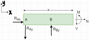
[latex]\sum{F_{x}} = 0=R_{Ax} + N\\ N = 0[/latex]
[latex]\sum{F_{y}}=0=R_{By}-R_{Ay}-V\\ \kern 1pc V=R_{By} -R_{Ay} \\ \kern 1pc V = 350 lb -210 lb\\ V= 140 lb[/latex]
now,
[latex]\sum{M_{A}}=0[/latex]
[latex]M =- \left( X_{B} \cdot R_{By} \right) + xV\\ \kern 1 pc = -\left(4 ft \cdot 350 lb\right) +\left( 7 ft \cdot140 lb\right) \\ \kern 1 pc = 980 lb ft- 1400 lb ft[/latex]
[latex]M =-420 lb ft[/latex]
Internal forces between C and B are [latex]N = 0, V= 140 lb, M=-420 lb ft[/latex]
d. Shear and Moment diagram
6. Review
There is no force in the x direction; therefore, it makes sense that the reaction force, RAx, is zero. Because the moment at A is generated by the person’s weight, RBy should be considerably large. As RBy is larger than the person’s weight, RAy should act downwards and would be of the same magnitude as the difference between RBy and the person’s weight to make the system stable.
For section b, the shear force between A and B is equal and opposite to the reaction force RAy. Similarly, with the concept of equilibrium, shear is equal and opposite to RAx, and the moment in this section is the negative of the moment generated at A.
It also makes sense that the shear between B and C is equal to the difference between RBy and RAy, and as expected, acting downward, thus it equals the weight of the person.
Example 6.3.7: Internal Forces and Shear/Moment Diagrams, Submitted by Odegua Obehi-Arhebun
1. Problem
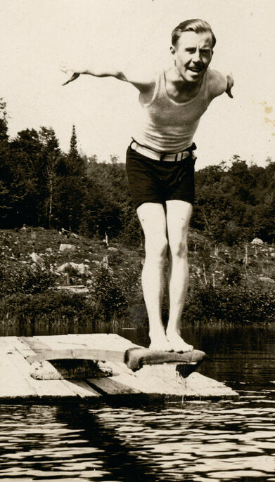
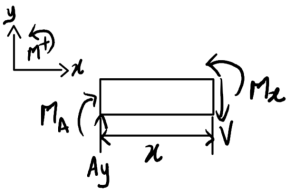
A bolt attached to a stair rail is to be removed by a technician. A solid wrench of length 30cm, arched horizontally to the bolt and assumed to be rigidly connected. The technician applies a downward vertical force of 200N at the free end of the wrench. Determine the internal normal force, shear force and bending moment at a point 0.15m along the wrench. Draw the full shear and moment diagram.
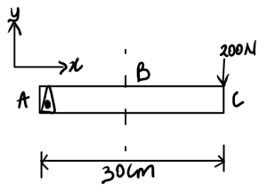
2. Draw
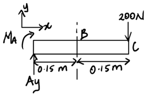
Free-body diagram:
3. Knowns and Unknowns
Knowns:
- F=200N
- L= 30cm => 0.3m
Unknowns:
- Internal normal force, shear force and bending moment at point B
- Shear + moment diagram
4. Approach
Solve for reaction forces at A, then take arbitrary sections between A and B and between B and C to derive V and M equations. Plot results.
5. Analysis
Solve for reaction forces:
[latex]\begin{aligned} \sum M_{A} &= 0 = -200\,\mathrm{N} \cdot 0.3\,\mathrm{m} - M_A \\ M_A &= -60\,\mathrm{Nm} \end{aligned}[/latex]
[latex]\begin{aligned} \sum F_{y} &= 0 = A_y - 200\,\mathrm{N} \\ A_y &= 200\,\mathrm{N} \end{aligned}[/latex]
[latex]\begin{aligned} \sum F_{x} &= 0 = N \\ N &= 0 \end{aligned}[/latex]
No force in the x-direction
Cut 1: With reaction forces known, cut a section between A and B
0m<x<0.15m
[latex]\begin{aligned} \sum F_{y} &= 0 = A_y - V \\ V &= A_y = 200\,\mathrm{N} \end{aligned}[/latex]
[latex]\begin{aligned} \sum M_x &= 0 = -M_A - A_y \cdot x +M(x) \\ M(x) &= 200x-60\,\mathrm{Nm} \end{aligned}[/latex]
You can also cut the section between B and C
0.15m<x<0.3m
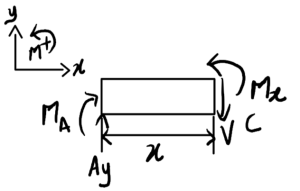
[latex]\begin{aligned} \sum F_{y} &= 0 = A_y - V \\ V &= A_y = 200\,\mathrm{N} \end{aligned}[/latex]
[latex]\begin{aligned} \sum M_x &= 0 = M_x - M_A- A_y \cdot x \\ M(x) &= 200x - 60\,\mathrm{Nm} \end{aligned}[/latex]
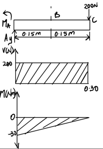
[latex]\begin{aligned} \text{At } x = 0, \quad &M = 0 \\ \text{At } x = 0.15\,\mathrm{m}, \quad &M = -30\,\mathrm{Nm} \\ \text{At } x = 0.3\,\mathrm{m}, \quad &M = 0 \end{aligned}[/latex]
Answer: N = 0, V = 200 N, Mx = 200x-60 Nm
6. Review
Negative sign for MA indicates that it should be in the other direction, as shown in the final diagram above. The shear force remains constant at 200N from A to C, then drops to zero at the end where the load is applied. The shear force is constant, hence it makes sense that the moment is linear.
Example 6.3.8: Internal Forces, Submitted by Celina Areoye
1. Problem
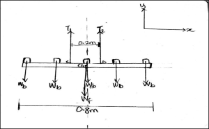
A Uniform rectangular light frame of mass 3kg and length 0.8m is suspended from the ceiling by two vertical rods. The rods are 0.2m apart and connected symmetrically to the ceiling plate. Also, there are 5 evenly spaced identical bulbs, each 0.5kg each mounted on the frame. Determine the tension in each vertical rod and the internal forces at the points where the vertical rod is connected to the frame.
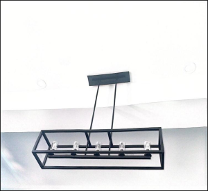
2. Draw
Free-body diagram:
3. Knowns and Unknowns
Knowns:
- Mass of frame (𝑀𝑓) = 3kg
- Length of frame (𝐿𝑓) = 0.8m
- Mass of each lightbulb (𝑀𝑏) = 0.5kg
Unknowns:
- Tension in each rod (𝑇1 𝑎𝑛𝑑 𝑇2)
- Internal forces at point D (𝑁D, 𝑉D, 𝑎𝑛𝑑 𝑀D)
4. Approach
Assuming the vertical rods are positioned centrally between the bulbs, and the internal forces at points C and D are the same (use any point to get the internal forces). First, find the tension and then use it in calculating internal forces.
5. Analysis
Weight of frame (𝑊𝑓) = 𝑀𝑓𝑔 = 3kg × 9.81m/s2 = 29.43N
Weight of one bulb (𝑊𝑏) = 𝑀𝑏𝑔 = 0.5kg × 9.81m/s2 = 4.905N
The bulbs are evenly spaced, so the distance between 2 bulbs (from centre to centre):
[latex]\frac{0.8\,\mathrm{m}}{4} = 0.2\,\mathrm{m}[/latex]
To get the tension in each rod:
[latex]+\uparrow \sum F_y = 0 \quad ; \quad T_1 + T_2 - 5W_b - W_f = 0[/latex]
Since the rods are connected symmetrically, they are equal (𝑇1 = 𝑇2 ), therefore:
To get the internal forces at point D, taking the right side of the diagram:
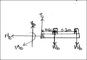
Since the rods are positioned centrally between the bulbs, the distance from point D to the bulb is
[latex]\frac{0.2\,\mathrm{m}}{2} = 0.1\,\mathrm{m}[/latex]
No force in the x-direction
6. Review
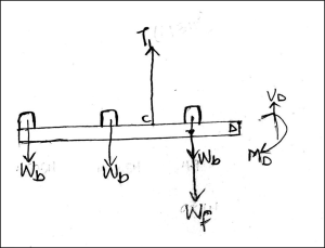
To check, taking the left side of the diagram
Example 6.3.9: Internal Forces, Submitted by Okino Itopa Farooq
1. Problem
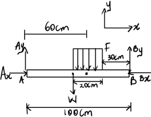
A uniform horizontal shelf of total length 100 cm and mass 2 kg is supported at both ends by pin connections. The shelf supports a group of 5 books placed together, each with a thickness of 4 cm and a mass of 0.5 kg. The collection of books is positioned such that it is located at a space 50 cm from the left end and 30 cm from the right end of the shelf. Assuming static equilibrium and neglecting the thickness of the shelf, determine the following at a point located 60 cm from the left end of the shelf:
- The shear force
- The normal (axial) force
- The bending moment

2. Draw
Free-body diagram:
3. Knowns and Unknowns
Knowns:
- Total length of shelf = 100cm = 1m
- Mass of shelf = 2kg
- Thickness of each book = 4cm = 0.04m
- Mass of each book = 0.5kg
- g = 9.81 m/s2
Unknowns:
- The shear force, normal force, and bending moment at 60cm (0.6m) from the left end of the shelf
4. Approach
First, resolve the distributed loads, then find reaction forces, and then calculate the internal forces
5. Analysis
Finding the force acting per m covered by the books
[latex]\left( \frac{0.5}{0.04} \right) \, \text{kg/m} = \left( \frac{0.5}{0.04} \right) \, \text{kg/m} \times 9.81 = 122.625 \, \text{N/m}[/latex]
Weight of the shelf
[latex]2 \, \text{kg} \times 9.81 \, \text{m/s}^2 = 19.62 \, \text{N}[/latex]
We first resolve the distributed load
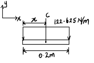
[latex]C = 122.625 \, \text{N/m} \times 0.2 \, \text{m} = 24.525 \, \text{N}[/latex]
[latex]X = \frac{0.2}{2} = 0.1 \, \text{m} \, \text{(0.6 m from A)}[/latex]
The new FBD should look like this:

Using equilibrium equations to find the reaction forces
Now that we know the Components Ay and By, we can start calculating the Shear, Normal and Bending moment at the point 0.6m from A, which will cut into the distributed load
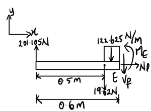
With Vf = Shear Force, Nf = Normal Force and Me = Bending Moment. The remaining distributed load is also resolved
[latex]122.625 \, \text{N/m} \times 0.1 \, \text{m} = 12.2625 \, \text{N}[/latex]
[latex]\text{(Located } 0.05 \, \text{m from the cut E and } 0.55 \, \text{m from A)}[/latex]
With all the info gathered, we can calculate the three forces.
Normal force is zero, as there are no horizontal forces to consider
For shear force:
[latex]\sum F_y = 0; \quad -201.105 - 19.62 - 12.2625 - V_F = 0\\ V_F = -233\, \text{N} = 233\, \text{N} \uparrow[/latex]
For Bending Moment:
[latex]\sum M_E = 0; \quad M_E + 122.625(0.05) + 19.62(0.1) + 201.105(0.6) = 0 \\ M_E = -129\, \text{N}\cdot\text{m}[/latex]
Therefore, Vf =-233N and ME =-129Nm
6. Review
Negative signs for Vf and ME indicate that it should go in the other direction. It makes sense that Ay and By go in opposite directions.
