
Chapter 1: Fundamental Concepts
1.6 Torque/Moment
1.6.1 Moments
Moments are created by a force acting at a distance from the center of rotation. There are three ways to calculate moments: scalar, vector, and using the right-hand rule. The first two methods will be presented in this section, and the third method will be discussed in section 3.1.3 on the right-hand rule.
A moment (sometimes called a torque) is defined as the “tendency of a force to rotate a body”. Where forces cause linear accelerations, moments cause angular accelerations. In this way, moments can be thought of as twisting forces.
The Vector Representation of a Moment:
Moments, like forces, can be represented as vectors and have a magnitude, a direction, and a “point of application”. For moments, however, a better name for the point of application is the axis of rotation. This will be the point or axis where we will determine all the moments.
Magnitude:
The magnitude of a moment is the degree to which the moment will cause angular acceleration in the body it is acting on. It is represented by a scalar (a single number). The magnitude of the moment can be thought of as the strength of the twisting force exerted on the body. When a moment is represented as a vector, the magnitude of the moment is usually explicitly labelled. Though the length of the moment vector also often corresponds to the relative magnitude of the moment.
The magnitude of the moment is measured in units of force times distance. The standard metric units for the magnitude of moments are newton meters, and the standard English units for a moment are foot pounds.
[latex]M = F \cdot d \\ \text{Metric: } \mathrm{N} \cdot \mathrm{m} \\ \text{English: } \mathrm{lb} \cdot \mathrm{ft}[/latex]
Direction:
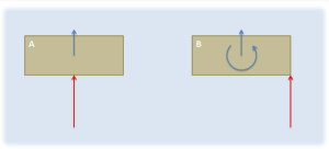
In a two-dimensional problem, the direction can be thought of as a scalar quantity corresponding to the direction of rotation the moment would cause. A moment that would cause a counter-clockwise rotation is a positive moment, and a moment that would cause a clockwise rotation is a negative moment.
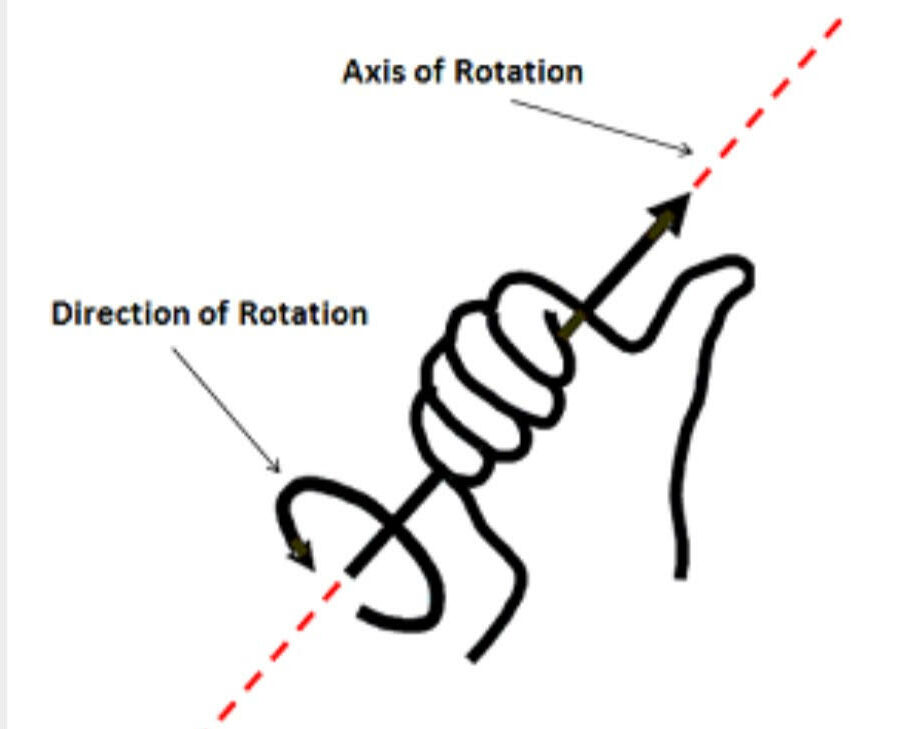
In a three-dimensional problem, however, a body can rotate about an axis in any direction. If this is the case, we need a vector to represent the direction of the moment. The direction of the moment vector will line up with the axis of rotation that moment would cause, but to determine which of the two directions we can use along that axis we have available, we use the right-hand rule. To use the right-hand rule, align your right hand as shown so that your thumb lines up with the axis of rotation for the moment and your curled fingers point in the direction of rotation for your moment. If you do this, your thumb will be pointing in the direction of the moment vector.
If we look back at two-dimensional problems, all rotations occur about an axis pointing directly into or out of the page (the z-axis). Using the right-hand rule, counter-clockwise rotations are represented by a vector in the positive z direction and clockwise rotations are represented by a vector in the negative z direction.
Axis of Rotation:
In engineering statics problems, we can choose any point/axis as the axis of rotation. The choice of this point will affect the magnitude and direction of the resulting moment, however, and the moment is only valid about that point.
Though we can take the moment about any point in a statics problem, if we are adding together the moments from multiple forces, all the moments must be taken about a common axis of rotation. Moments taken about different points cannot be added together to find a ‘net moment’
Additionally, if we move into the subject of dynamics, where bodies are moving, we will want to relate moments to angular accelerations. For this to work, we will need to take the moments either about a single point that does not move (such as the hinge on a door) or we will need to take the moments about the center of mass of the body. Summing moments about other axes of rotation will not result in valid calculations.
Calculating Moments:
We will have two main options to calculate the moment that a force exerts on a body: scalar methods and vector methods. Scalar methods are generally faster for two-dimensional problems where a body can only rotate clockwise or counterclockwise, while vector methods are generally faster for three-dimensional problems where the axis of rotation is more complex.
Given any point on an extended body, if there is a force acting on that body that does not travel through that point, then that force will cause a moment about that point. As discussed on the moments page, a moment is a force’s tendency to cause rotation.
Source: Engineering Mechanics, Jacob Moore et al., http://mechanicsmap.psu.edu/websites/1_mechanics_basics/1-5_moments/moments.html
1.6.2 Scalar Method in 2 Dimensions
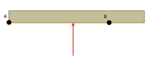
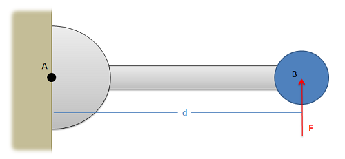
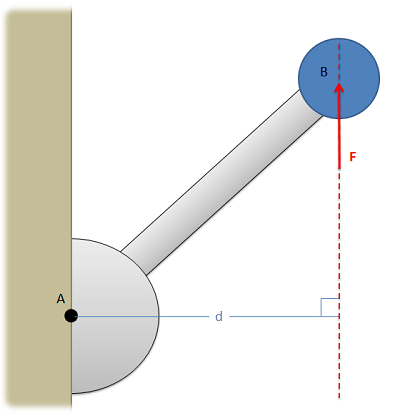
In discussing how to calculate the moment of a force about a point via scalar quantities, we will begin with the example of a force on a simple lever as shown below. In this simple lever there is a force on the end of the lever, distance d away from the center of rotation for the lever (point A) where the force has a magnitude F.
When using scalar quantities, the magnitude of the moment will be equal to the perpendicular distance between the line of action of the force and the point about which we are taking the moment.
[latex]M=F\ast d[/latex]
To determine the sign of the moment, we determine what type of rotation the force would cause. In this case, we can see that the force would cause the lever to rotate counterclockwise about point A. Counterclockwise rotations are caused by positive moment,s while clockwise rotations are caused by negative moments.
Another important factor to remember is that the value d is the perpendicular distance from the force to the point we are taking the moment about. We could measure the distance from point A to the head of the force vector, or the tail of the force vector, or really any point along the line of action of force F. The distance we need to use for the scalar moment calculation, however, is the shortest distance between the point and the line of action of the force. This will always be a line perpendicular to the line of action of the force, going to the point we are taking the moment about.
Source: Engineering Mechanics, Jacob Moore et al., http://mechanicsmap.psu.edu/websites/3_equilibrium_rigid_body/3-1_moment_scalar/moment_scalar.html
If the position vector and force aren’t exactly 90 degrees, the equation T = |r| |F| sin Θ can be helpful and still produce a scalar number for moment or torque. This would be good if we had simple systems, such as opening a door or spinning a top. What happens when you have a rotating door and a few people try to go through it? Or a force that isn’t exactly along two axes? We’ll use vectors as shown in the next section to solve that.
1.6.3 Vector Method in 3 Dimensions
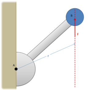
An alternative to calculating the moment via scalar quantities is using the vector or cross product methods. For simple two-dimensional problems, using scalar quantities is usually easier, but for more complex problems, using the cross product method is usually easier. The cross product method for calculating moments says that the moment vector of a force about a point will be equal to the cross product of a vector r from the point to anywhere on the line of action of the force and the force vector itself.
[latex]\vec M=\vec r\times\vec F[/latex]
A big advantage of this method is that r does not have to be the shortest distance between the point and the line of action; it goes from the point to any part of the line of action. For any problem, there are many possible r vectors, though, because of the way the cross product works, they should all result in the same moment vector in the end.
It is important to note here that all quantities (r, F and M) are vectors. Before you can solve for the cross product, you will need to write out r and F in vector component form. Also, even for two-dimensional problems, you will need to write out all three components of the r and F vectors. For two-dimensional problems, the z components of the r and F vectors will simply be zero, but those values are necessary for the calculations.
The moment vector you get will line up with the axis of rotation for the moment, where you can use the right-hand rule to determine if the moment is going clockwise or counterclockwise about that axis.
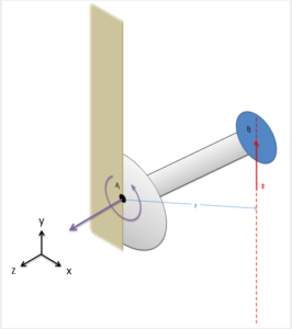
Finally, it is also important to note that the cross product, unlike multiplication, is not commutative. This means that the order of the vectors matters, and r cross F will not be the same as F cross r. It is important to always use r cross F when calculating moments.
Source: Engineering Mechanics, Jacob Moore et al., http://mechanicsmap.psu.edu/websites/3_equilibrium_rigid_body/moment_vector/momentvector.html
Whether you use scalars: M = |r| |F| sinΘ or vectors: M = r x F, you can solve most moment/torque problems. The scalar method is faster for 2-D problems, especially if the vectors are at 90-degree angles from each other (sin 90º = 1). The vector method is more robust, especially if there are additional angles involved. There is the potential to make errors, so it’s recommended to use the Step 6 Review step to try multiple methods to ensure your answer is correct.
See the examples in section 1.8, as many of them concern moments.
Key Takeaways
Basically: There are three methods to calculate moments, two of which were discussed here. Moments or Torque is created by a force acting at some distance from an axis of rotation.
Application: When you are opening a heavy door, you push on the door. If you push closer to the axis of rotation, you’ll need a bigger force to make it move. If you push further away from the axis (so r is bigger), the force can be smaller to make the same motion occur.
Looking ahead: Moments apply when rigid bodies are involved, so we’ll pick up moments again in Chapter 3.1.3, when you’ll learn the third way to calculate moments (torque).
