
Chapter 5: Trusses
5.5 Examples
Here are examples from Chapter 5 to help you understand these concepts better. These were taken from the real world and supplied by FSDE students in Summer 2021. If you’d like to submit your own examples, please send them to the author eosgood@upei.ca.
Example 5.5.1: Method of Sections, Submitted by Riley Fitzpatrick
1. Problem
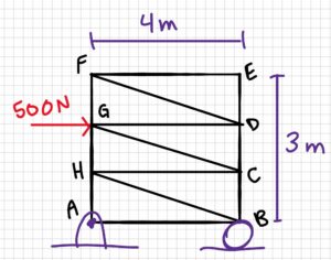
A flower cart at a local garden center is being pushed with a force of 500N at joint G. Its back wheels (A) are locked, so it is not moving. There is 1 meter of space between each of the four shelves in height, and each shelf is four meters long.
a) Calculate the reaction forces of the locked wheels and the unlocked wheels.
b) Calculate the load carried by FCG, and whether it is in tension or compression
Which method did you use, joints or sections? Which is faster for the style of questions? How would your strategy change if you were calculating the load in each member?

2. Draw
Sketch:
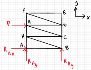
Free-body Diagram:
3. Knowns and Unknowns
Knowns:
- P = 500 N
- Width = 4 m
- Total height = 3 m
Unknowns:
- RAx
- RAy
- RBy
- FCG
4. Approach
Part a: Determine reaction forces using equilibrium equations
Part b: Calculate FCG using the method of sections. Make a cut, then solve internal forces using equilibrium equations
5. Analysis
Part a:
Solving for RAx:
[latex]\sum F_x=0=P+R_{Ax}\\R_{Ax}=-P\\R_{Ax}=-500N[/latex]
Solving for RBy:
[latex]\sum M_A=0=(r_{BA}\cdot R_{By})-(r_{GA}\cdot P)\\r_{BA}\cdot R_{By}=r_{GA}\cdot P\\R_{By}=\frac{r_{GA}\cdot P}{r_{BA}}\\R_{By}=\frac{2m\cdot 500N}{4m}\\R_{By}=250N[/latex]
Solving for RAy:
[latex]\sum F_y=0=R_{By}+R_{Ay}\\R_{Ay}=-R_{By}\\R_{Ay}=-250N[/latex]
The answers we got that were negative numbers mean that the direction of the vector is drawn wrong on our original diagram (in reference to our coordinate frame). This makes sense as RAy and RBy are the only external forces in the y direction, so they have to cancel each other for the equilibrium equations to be true (Same for the vectors in the x direction.) Therefore, one of them should have a negative direction. We will leave this answer as is for now, but the next time we draw the system, we will change the direction of the arrow.
[latex]\underline{R_{Ax}=-500N,\; R_{Ay}=-250N, \; R_{By}=250N}[/latex]
Part b:
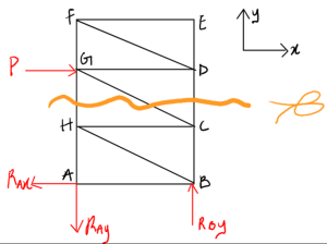
Firstly, we redraw the diagram, changing the direction of the RAy and RAx. Then, since we are using the method of sections, we make a cut so that the member FCG (the one we want to find) is cut.
Now we redraw, choosing one of the pieces from the cut. Here, the top half is chosen, but you could also choose the bottom half and get the right answer. The only reason the top half was chosen here is because there are fewer external forces to consider for the top.
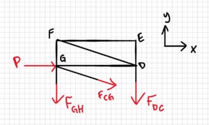
Solve for the member we are looking for:
[latex]\sum F_x=0=P+\frac{4}{\sqrt{17}}F_{CG}\\\frac{4}{\sqrt{17}}F_{CG}=-P\\F_{CG}=-P(\frac{\sqrt{17}}{4})\\F_{CG}=-500N(\frac{\sqrt{17}}{4})\\F_{CG}=-515.388N[/latex]
Again, the number we get is negative. The way we drew FCG originally was as if the member was in tension. The negative number just means that it is actually compression, not tension.
[latex]\underline{F_{CG}=515 \text{N (Compression)}}[/latex]
Part C:
For part b, I used the method of sections, as it would be the fastest method. The method of joints would require the lower joints to be solved first, which would be a much slower process, whereas with this method, a simple cut can be made, and the member’s load can be quickly solved using equilibrium equations. Had the question asked for all member loads to be solved, however, the method of joints would have been the faster approach.
6. Review
Part a:
RAx is equal and opposite to P so we know it is correct, and the value of RBy should also be correct as its moment about A (250 * 4m = 1000 Nm), is equal and opposite to the moment of P about A, (500 N * 2 m = 1000 Nm). as RAy is equal and opposite to RBy it is also correct.
Part b:
The x component of the calculated value of FCG is equal in magnitude to P (see equation below), and it is the only cut member acting in the x direction. Therefore, it must be correct.
[latex]\frac{4}{\sqrt{17}}(515 N)=500 N[/latex]
Part C:
The method of sections allows you to solve a very specific area of the system’s internal forces (the members that are cut), whereas the method of joints usually requires you to solve most, if not all, of the internal forces of the system. Therefore, the method of sections is the most efficient for finding the internal forces of specific parts of the system, whereas the method of joints is more efficient for solving the whole system.
Example 5.5.2: Zero-Force Members, Submitted by Michael Oppong-Ampomah
1. Problem
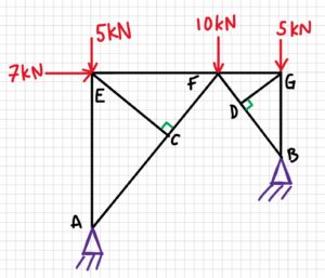
A bridge with uneven ground has been built as shown below. Force is applied at three points on the top of the bridge.
a) Find any zero-force members
b) What purpose do these members serve?
2. Draw
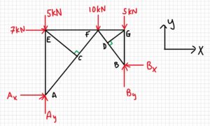
Free-body diagram:
3. Knowns and Unknowns
Knowns:
- All of the known values do not mean anything – we only need to know where the forces exist
Unknown:
- Which members are zero-force
4. Approach
Look at each joint and determine how many forces are in each direction. If there is only one force in a direction, that member is zero-force.
5. Analysis
Part a:
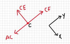
Let’s start with joint C. If we think of the forces acting in the x and y directions as shown below by the coordinate frame, we see that there are two forces acting in the y direction, and only one in the x direction. Therefore, assuming the joint is in static equilibrium, member CE is a zero-force.
If we do the same type of analysis for the other joints and remove the zero-force members, the structure now looks like this:
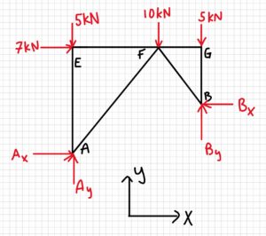
After one more analysis of the joints, we find one more zero-force member, as shown below.
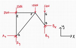
Answer: CE, DG, and FG are zero-force members.
Part b:
Zero-force members exist to provide stability to the truss, to keep the shape rigid.
6. Review
Although the new truss (without zero-force members) looks strange, there are no joints where there’s only one force in one direction; therefore, there are no more zero-force members.
Example 5.5.3: Method of Joints, Submitted by Deanna Malone
- Problem
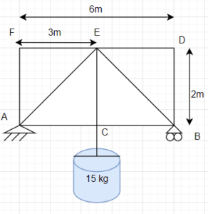
A small truss bridge is over a river, and it has a bucket full of water hanging off the middle. The mass of the water bucket is 15 kg.
a. Solve for the reaction forces.
b. Use the method of joints to solve each member.
c. Draw forces and how they act.
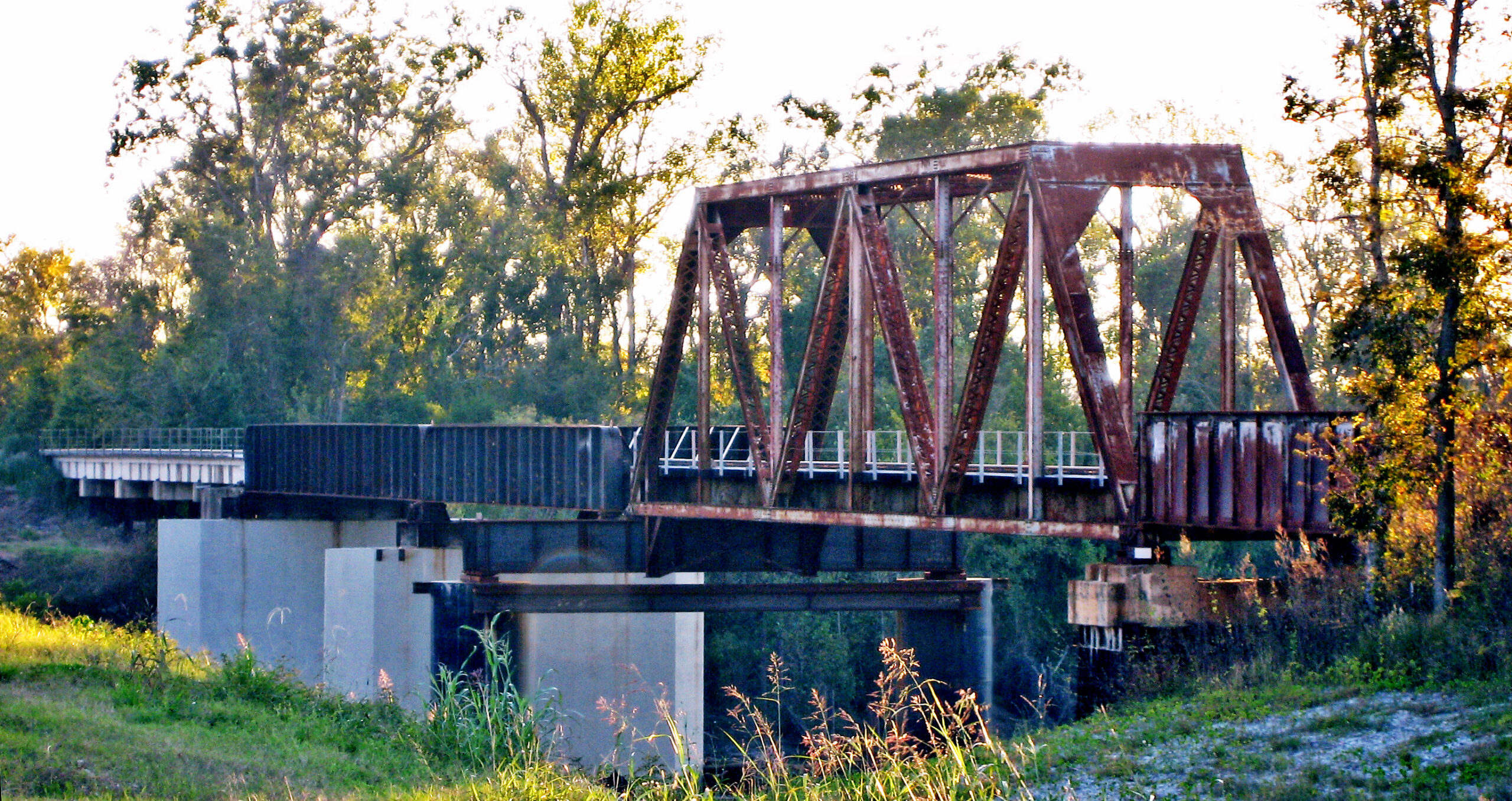
In the real world, the truss bridge might be similar to this,
2. Draw
3. Knowns and Unknowns
Knowns:
- Fg = 15 kg . 9.81 m/s2 = 147.15 N
- rAF = rBD = rCE =2 m
- rDF = rAB = 6 m
Unknowns:
- RAx
- RAy
- RBy
- FEF
- FED
- FBD
- FBE
- FCE
- FAE
- FAC
- FBC
- FAF
4. Approach
First, use the equilibrium equations to find the reaction forces. Apply these reaction forces in the method of joints to find the force of each member.
5. Analysis
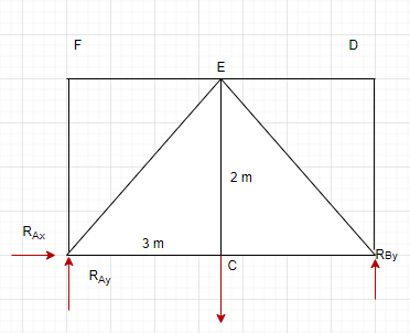
a. Calculating the reaction forces using the equilibrium equations and the diagram.
[latex]\sum F_x=0=R_{Ax}\\R_{Ax}=0N[/latex]
Solving for RBy:
[latex]\sum M_A=0= -(r_{AC}\cdot F_g)+(r_{AB}\cdot R_{By})\\r_{AB}\cdot R_{By}=r_{AC}\cdot F_g[/latex]
[latex]R_{By}=\frac{r_{AC}\cdot F_g}{r_{AB}}\\R_{By}=\frac{3m\cdot 147.15 N}{6m}[/latex]
[latex]R_{By}=73.575 N[/latex]
Solving for RAy:
[latex]\sum F_y=0=R_{By}+R_{Ay} -F_g\\R_{Ay}=F_g-R_{By}\\R_{By}=73.575N[/latex]
b. FAF, FEF, FDE, FBD are zero force members because for joints F and D, there are only 2 members each, and there is no external load.
Finding the angle between AC and AE:
tan θ = rCE/rAC
therefore, θ = 33.7 °
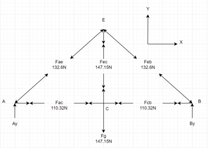
Analyzing joint A:
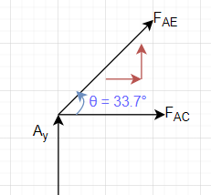
[latex]\sum F_y=0 = R_{Ay}+ F_{AE}\cdot sin 33.7 \\ =\frac{-73.575 N}{sin 33.7}[/latex]
[latex]F_{AE} = -132.6 N[/latex]
[latex]\sum F_x=0 = F_{AC} + F_{AE} cos 33.7\\ F_{AC}=132.6N\cdot \cos {33.7}[/latex]
[latex]F_{AC} = 110.32 N[/latex]
Analyzing Joint C:
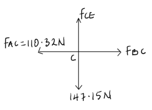
From the FBD,
FAC= FBC = 110.32 N
Also, Fg =FCE = 147.15 N
Analyzing Joint B
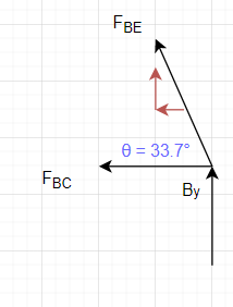
[latex]\sum F_y=0 = R_{By} +F_{BE}\cdot sin 33.7[/latex]
[latex]F_{BE} = -132.6 N[/latex]
[latex]\sum F_x=0 = F_{BC} -F_{BE} cos 33.7\\ F_{BC}=132.6N\cdot \cos {33.7}[/latex]
[latex]F_{BC} = 110.32 N[/latex]
c.
6. Review
The answers make sense because FCEis in tension as imagined due to the weight of the bucket. Members AC and BC are under reaction forces, are equally under tension, and members AE and BE are balanced by compression. The identified zero-force members also make sense due to the rules being met.
Example 5.5.4 Method of Joints, Submitted by Luke McCarvill
1. Problem
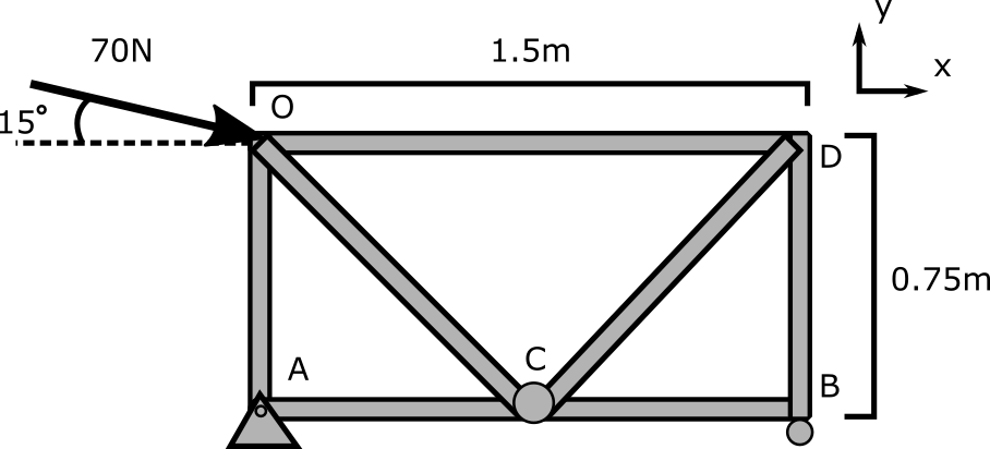
Jeffery is unsuccessfully pushing a 2-dimensional shopping cart shown below with a force of 70N. It is made up of steel (8g/cm3) rods with 2cm diameters. The wheel of the cart that is closest to him is stuck (pinned) while the front wheel is free to roll (roller). The total height of the cart is 0.75m, and its total length is 1.5m.
What is the total mass of the cart? (For the purposes of the equilibrium equations, assume the total weight acts only at the centre point of the system, and otherwise the rods are massless.) What are the reaction forces on the wheels?
2. Draw
3. Knowns and Unknowns
Knowns:
• [latex]P = 70\,N[/latex]
• [latex]\sum M = 0[/latex]
• [latex]h = 0.75\,m[/latex]
• [latex]\theta_p = 15^\circ[/latex]
• [latex]d_{\text{rod}} = 2\,\text{cm (diameter)}[/latex]
• [latex]\sum F = 0[/latex]
• [latex]\rho = 8.00\,\text{g/cm}^3[/latex]
• [latex]V_{\text{cylinder}} = \pi r^2 h[/latex]
Unknowns:
• [latex]m_{\text{tot}} = \, ?[/latex]
• [latex]P_x = \, ?[/latex]
• [latex]P_y = \, ?[/latex]
• [latex]R_{Ax} = \, ?[/latex]
• [latex]R_{Ay} = \, ?[/latex]
• [latex]R_{By} = \, ?[/latex]
• [latex]F_g = \, ?[/latex]
4. Approach
Use trigonometry and equilibrium equations, as well as the method of joints, to calculate unknowns
5. Analysis
Finding total mass:
There are four 75cm rods, two rods that are [latex]75\sqrt{2}[/latex]cm, and one rod that is 1.5m long, all of which have a diameter of 2cm. The total mass is therefore [latex]8g/cm^3 \cdot ((4 \pi \cdot (1cm)^2\cdot (75cm) + 2\pi\cdot (1cm)^2 \cdot \\ (75 \sqrt(2)cm) + \pi (1cm)^2 \cdot (150cm)) \\ \approx 16,641g = 16.641kg = m_{tot}[/latex]
Fg can then be found using [latex]F_g = g \cdot m_{tot} = -9.81m/s^2 \cdot 16.641kg \approx -163.25N[/latex]
The sum of forces and moments can now be used to determine reaction forces
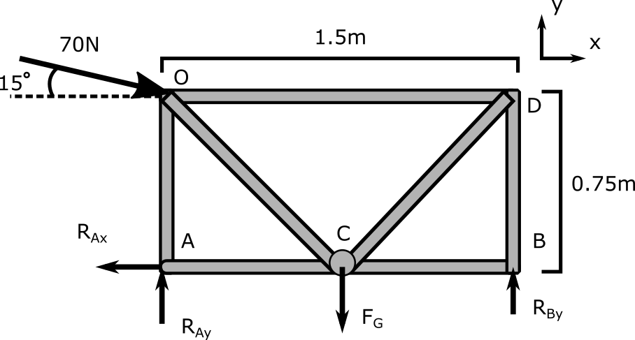
[latex]\sum F_x = P_x - R_{Ax} \\ R_{Ax} = P \cdot cos(\theta) = 70N cos(15^\circ) \\ R_{Ax} \approx 67.6N[/latex]
[latex]\sum F_y = -F_g - P_y + R_{Ay} + R_{By} = 0[/latex]
With two unknowns, the sum of moments must be considered. Summing moments around point A finds:
[latex]\sum M_A = 0 = -(0.75m \cdot Pcos(\theta)) - (0.75m \cdot F_g) + (1.5m \cdot R_{By})[/latex]
[latex]\sum M_A = 0 = -(0.75m \cdot 70N cos(15^\circ)) - (0.75m \cdot 163.25N) + (1.5m \cdot R_{By})[/latex]
[latex]R_{By} \approx 115.43N[/latex]
Sum of Forces in Y can now be used to find RAy
[latex]F_y = -F_g - P_y + R_{Ay} +R_{By} = 0[/latex]
[latex]R_{Ay} \approx 65.94N[/latex]
The method of joints can now be used to determine if any zero-force members exist in the shopping cart.
Looking at Point A, it can be found that [latex]F_{AO} = 65.94\,N[/latex] in compression and [latex]F_{AC} = 67.6\,N[/latex] in tension. Continuing through each joint, it can be found that member CB is a zero-force member as point B only has one component in the X direction, which, in a static system, implies that the force must be zero.
6. Review
Given the high weight of the cart creating a large Fg and the applied force of 70N, the reaction forces found and the internal forces all seem to be of appropriate magnitude and direction.
Example 5.5.5: Method of Sections, Submitted by Liam Murdock
1. Problem
2. Sketch
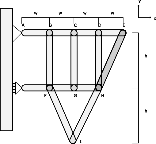
Draw a free-body diagram of the truss with a slice through CD, GH, and IH.
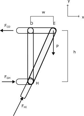
3. Knowns and Unknowns
Knowns:
- w = 0.1 m
- h = 0.2 m
- FCD = -25 N
- FGH = 15 N
Unknowns:
- FHI =?
- dHI = ?
- P =?
- m = ?
4. Approach
Use the method of sections to show internal forces and analyze as a rigid body.
5. Analysis
First, the distance dHI can be found:
[latex]d_{HI} = \sqrt{(0.1 m)^2 + (0.2 m)^2} \\ d_{HI} = 0.2236 m[/latex]
This value can be used to find the equivalents to cosθ and sinθ:
[latex]\cos{\theta} = \frac{0.1 m}{0.2236 m} \\ \sin{\theta} = \frac{0.2 m}{0.2236 m}[/latex]
The sum of forces in the X direction can be used to determine the value of FHI:
[latex]\sum F_x = 0 = -F_{CD} + F_{GH} + F_{HI} \cdot \cos{\theta} \\ F_{HI} = \frac{(F_{CD} - F_{GH})}{\cos{\theta}} \\ F_{HI} = \frac{0.2236 m}{0.1 m} \cdot (25 N - 15 N) \\ F_{HI} = 22.36N[/latex]
The sum of forces in the Y direction can now be used to determine the value of P:
[latex]\sum F_y = 0 = -P + F_{HI} \cdot \sin{\theta} \\ P = F_{HI} \cdot \sin{\theta} \\ P = (22.36 N) \cdot \frac{0.2 m}{0.2236 m} \\ P = 20 N[/latex]
The mass can now be simply found by dividing the force by gravity:
[latex]P = mg \\ m = \frac{P}{g} \\ m = \frac{20 N}{9.81 \frac{m}{s^2}} \\ m = 2.04 kg[/latex]
6. Review
A brief review of this question is the sign and magnitude of the result. The force generated by the mass pushes downwards with gravity, which is expected. The magnitude of the mass, while defining this shelf as one that is particularly flimsy, is a reasonable mass.
