
Chapter 6: Internal Forces
6.1 Types of Internal Forces
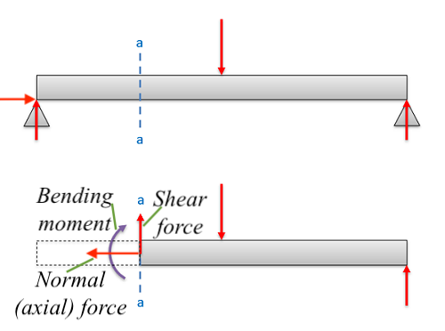
When you make a cut in an object, similar to a fixed reaction, we describe what is happening at that point using one horizontal force (called normal force), one vertical force (called shear force), and a bending moment.
6.1.1 Types of Internal Forces
There are 3 types of internal forces (& moments):
- Normal force (N) – the horizontal force we calculated in trusses in the last chapter
- Shear force (V) – the vertical force that changes based on the applied loads
- bending moment (M) – changes based on the applied loads and applied moments
Normal force is represented by ‘N’. Shear force, the vertical force, is represented by ‘V’. Bending moment is ‘M’. Normal and shear have units of N or lb, and bending moment has units of Nm or ft-lb. The following table summarizes information on internal forces (and moments).
| Force/Moment | Abbreviation | Unit | Directions for a horizontal beam |
| Normal Force | N | N or lb | horizontal |
| Shear Force | V | N or lb | vertical |
| Moment | M | Nm or ft-lb | rotation |
Note that for a vertical column, the normal force would be vertical. For this reason, the normal force is often called ‘axial’ as in: along the axis. The shear force for a column would be horizontal and is sometimes called ‘transverse’.
This is for a 2d analysis of the beam, assuming there is negligible loading in the third dimension.
When a beam or frame is subjected to transverse loadings, the three possible internal forces that are developed are the normal or axial force, the shearing force, and the bending moment, as shown in section k of the cantilever of the figure below. To predict the behaviour of structures, the magnitudes of these forces must be known. In this chapter, the student will learn how to determine the magnitude of the shearing force and bending moment at any section of a beam or frame and how to present the computed values in a graphical form, which is referred to as the “shearing force” and the “bending moment diagrams.” Bending moment and shearing force diagrams aid immeasurably during design, as they show the maximum bending moments and shearing forces needed for sizing structural members.
Normal Force
The normal force at any section of a structure is defined as the algebraic sum of the axial forces acting on either side of the section.
Shearing Force
The shearing force (SF) is defined as the algebraic sum of all the transverse forces acting on either side of the section of a beam or a frame. The phrase “on either side” is important, as it implies that at any particular instance, the shearing force can be obtained by summing up the transverse forces on the left side of the section or on the right side of the section.
Bending Moment
The bending moment (BM) is defined as the algebraic sum of all the forces’ moments acting on either side of the section of a beam or a frame.
Source: Internal Forces in Beams and Frames, Libretexts. https://eng.libretexts.org/Bookshelves/Civil_Engineering/Book%3A_Structural_Analysis_(Udoeyo)/01%3A_Chapters/1.04%3A_Internal_Forces_in_Beams_and_Frames
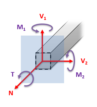
In 3 dimensions, there are:
- 1 normal force (N)
- 2 shear forces (V1 & V2), and
- 3 bending moments (M1, M2, & T – torsion).
6.1.2 Sign Convention
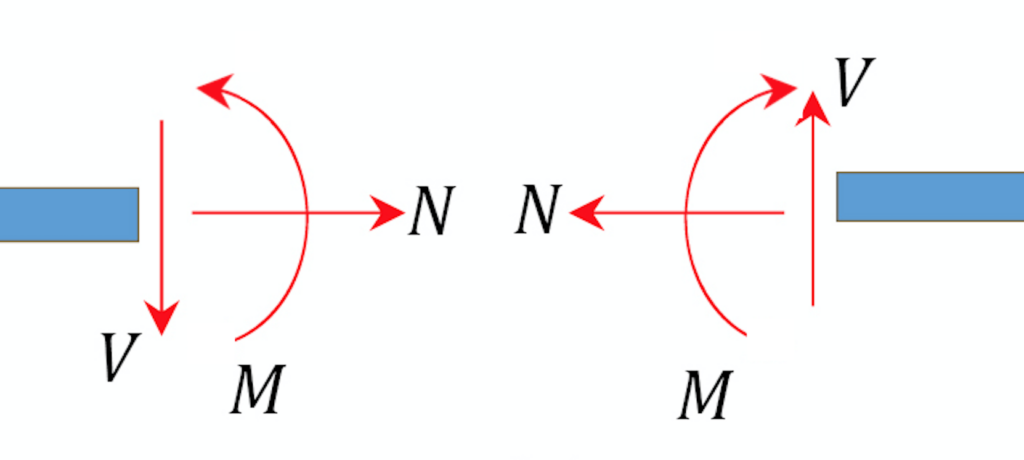
So that there is a standard within the industry, a sign convention is necessary so we agree on what is positive and what is negative. On the right, shear-up is positive. Notice that both of the following figures show the identical sign convention.

When you look at the beam as a whole (in the figure below), positive shear is right side down. When you cut into the beam, for it to be in static equilibrium, the positive shear must then be up on the right to be equal and opposite to the overall motion.
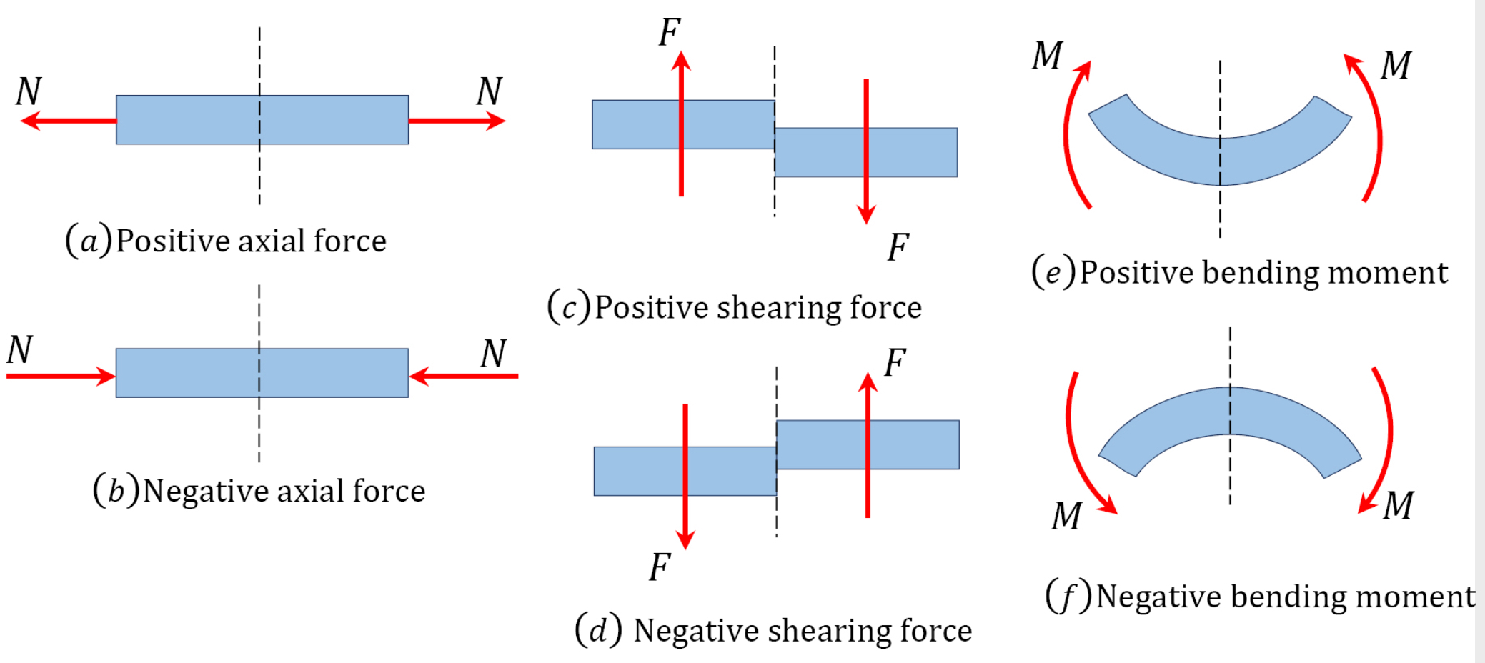
Axial (Normal) Force
An axial force is regarded as positive if it tends to tier the member at the section under consideration. Such a force is regarded as tensile, while the member is said to be subjected to axial tension. On the other hand, an axial force is considered negative if it tends to crush the member at the section being considered. Such force is regarded as compressive, while the member is said to be in axial compression.
Shear Force
A shear force that tends to move the left of the section upward or the right side of the section downward will be regarded as positive. Similarly, a shear force that has the tendency to move the left side of the section downward or the right side upward will be considered a negative shear force.
Bending Moment
A bending moment is considered positive if it tends to cause concavity upward (sagging). If the bending moment tends to cause concavity downward (hogging), it will be considered a negative bending moment.
Source: Internal Forces in Beams and Frames, Libretexts. https://eng.libretexts.org/Bookshelves/Civil_Engineering/Book%3A_Structural_Analysis_(Udoeyo)/01%3A_Chapters/1.04%3A_Internal_Forces_in_Beams_and_Frames
6.1.3 Calculating the Internal Forces
To solve the internal forces at a certain point along the beam,
- Find the external & reaction forces
- Make a cut.
- In a FBD of one side of the cut, add the internal forces (and moments) using the positive sign convention.
- Use the equilibrium equations to solve for the unknown internal forces and moments.
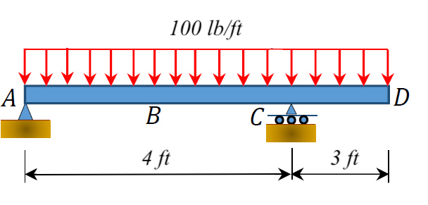
Example: For the following distributed load, a) what are the reaction forces? b) What are the internal forces at the midpoint B between the reaction forces?
1. Solve external forces:
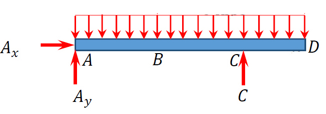
[latex]\sum F_{X}=A_{x}=0[/latex]
[latex]\sum F_{y}=A_{y}+C-\omega L=0[/latex]
[latex]\sum M_{A}=-(\omega L)\left(\frac{L}{2}\right)+d_{A C} C=0[/latex]
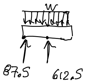
[latex]C = \left(\frac{\omega L^2}{2d_{A C}}\right) = \frac{(100 \frac{lb}{ft} )*(7ft)^2}{2 * (4ft)} = 612.5 lb \text{ (+j direction)}[/latex]
[latex]A_y = \omega*L- C = (100 \frac{lb}{ft})*(7 ft) - 612.5 lb = 87.5 lb \text{ (+j direction) }[/latex]
[latex]\underline{A_x = 0 \qquad A_y = 87.5 \text{ (+j )} \qquad C = 612.5 lb \text{ (+j )} }[/latex]
2. Make a cut at B.
3. In a FBD of one side of the cut, add the internal forces (and moments) using the positive sign convention.
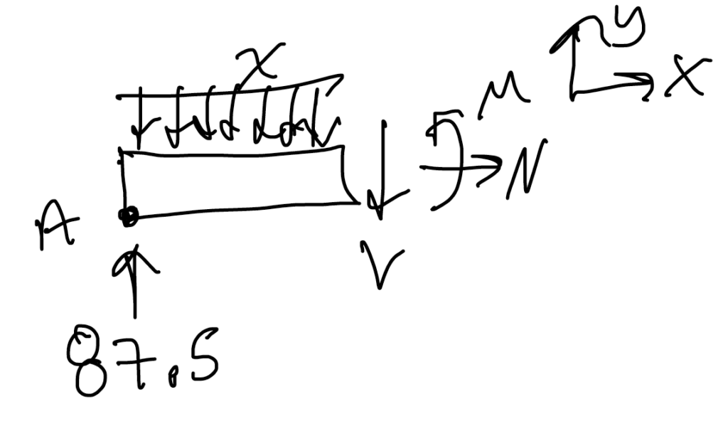
4. Use the equilibrium equations to solve for the unknown internal forces and moments.
For just this portion, the force from intensity is: Fw = ( 100 lb/ft ) * ( 2 ft) = 200 lb and acts 1 ft from the left, so the moment due to intensity is: Mw = w * 2 ft * 1 ft = Fw * 1 ft = ( 100 lb/ft ) * ( 2 ft) * (1 ft) = 200 ft-lb
[latex]\sum F_y = 87.5 lb - 200 lb - V = 0 \\ V = -112.5 lb \text{ (- indicates going up not down)}[/latex]
[latex]\sum M_A = - (w * 2 ft) * (1 ft) - V * (2 ft) + M = 0 \\ M = (100 \frac{lb}{ft}) * 2 ft + (-112.5 lb) * (2 ft) \\ M = 200 ft \cdot lb - 225 ft \cdot lb \\ M = -25 ft \cdot lb \text{ (- indicates going reverse direction)}[/latex]
[latex]\underline{N = 0 \qquad V = -112.5 lb \text{ (+j )} \qquad M = -25 ft \cdot lb \text{ (clockwise)} }[/latex]
Key Takeaways
Basically: The internal forces (and moments) for a 2d beam are: shear, normal, and bending moment. There is a positive sign convention to use when making a cut along a beam to determine the forces inside: on the left, shear down, normal out, moment up.
Application: A bridge that has different loads applied (from cars, trucks, lampposts, etc). Use this method to calculate the internal loads at a particular point of interest.
Looking Ahead: In the next section, we’ll look at how to calculate the internal force across the whole beam and display the results graphically.
